Firmware
Overview
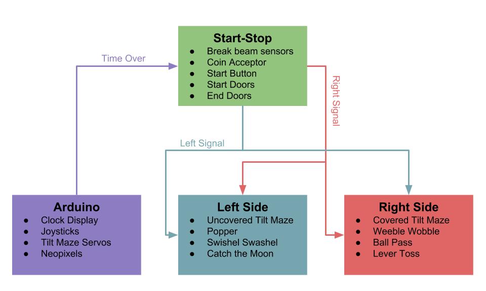
The firmware for this project is split between three PIC microcontrollers and an Arduino. One microcontroller controls the start and stop conditions, the other two microcontrollers control the obstacles which are loosely split up between the right and left side, and the Arduino controls the joysticks, the two tilt mazes, and the countdown timer. All of the code for this project can be found on our GitHub repository located here.
Start - Stop Microcontroller
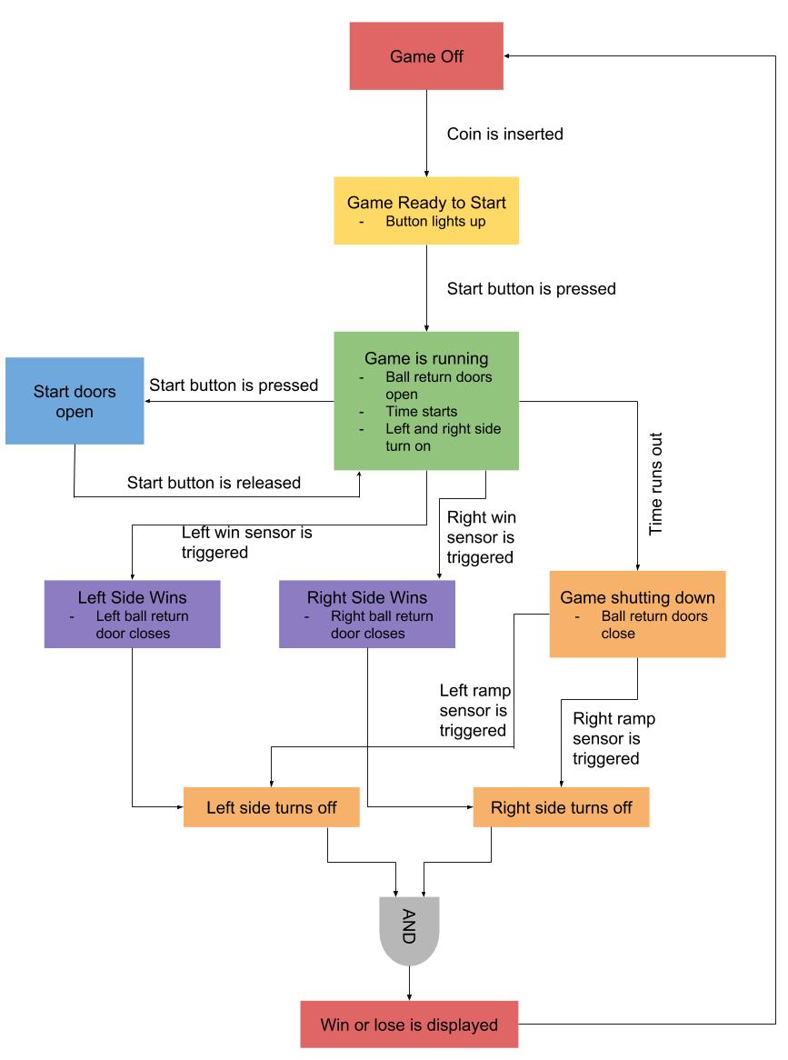
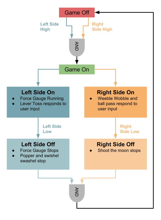
The start-stop microcontroller controls which sides of the game are on. When the game first boots up, both sides of the game is off. The player then has to insert a coin and press the start button to begin the game which turns on both sides of the game. The sides of the game remain on until either a side wins, or time runs out and the remaining balls have either reached the goal or fallen off the obstacles. The sides remain on when time has run out until the balls are back in the ball return. This gives the players one last chance to win and also ensures that the balls don't get stuck in any of the obstacles. Once both balls are inside of the game, the game shuts off and the right side pin goes high if the players won, and the left side pin goes high if the players lost.
Left Side
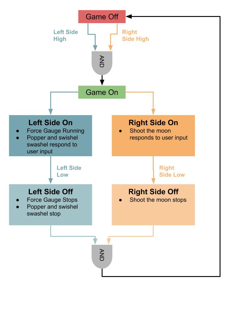
The left microcontroller controls the popper, the force gauge for the popper, the swishel swashel, and shoot the moon. Aside from half of swishel swashel, these obstacles are the ones that the left player has control of.
The game remains off until both the right and left signal pins go high. At which point both sides turn on. Each side remains on and continues to accept user input until the signal pin for that side goes low. The game fully turns off when both the left and right side signal pins go low.
Right Side
The right microcontroller controls the lever toss, the force gauge for the lever toss, the weeble wobble, and the ball pass. Aside from half of ball pass, these obstacles are the ones that the left player has control of.
The game remains off until both the right and left signal pins go high. At which point both sides turn on. Each side remains on and continues to accept user input until the signal pin for that side goes low. The game fully turns off when both the left and right side signal pins go low.
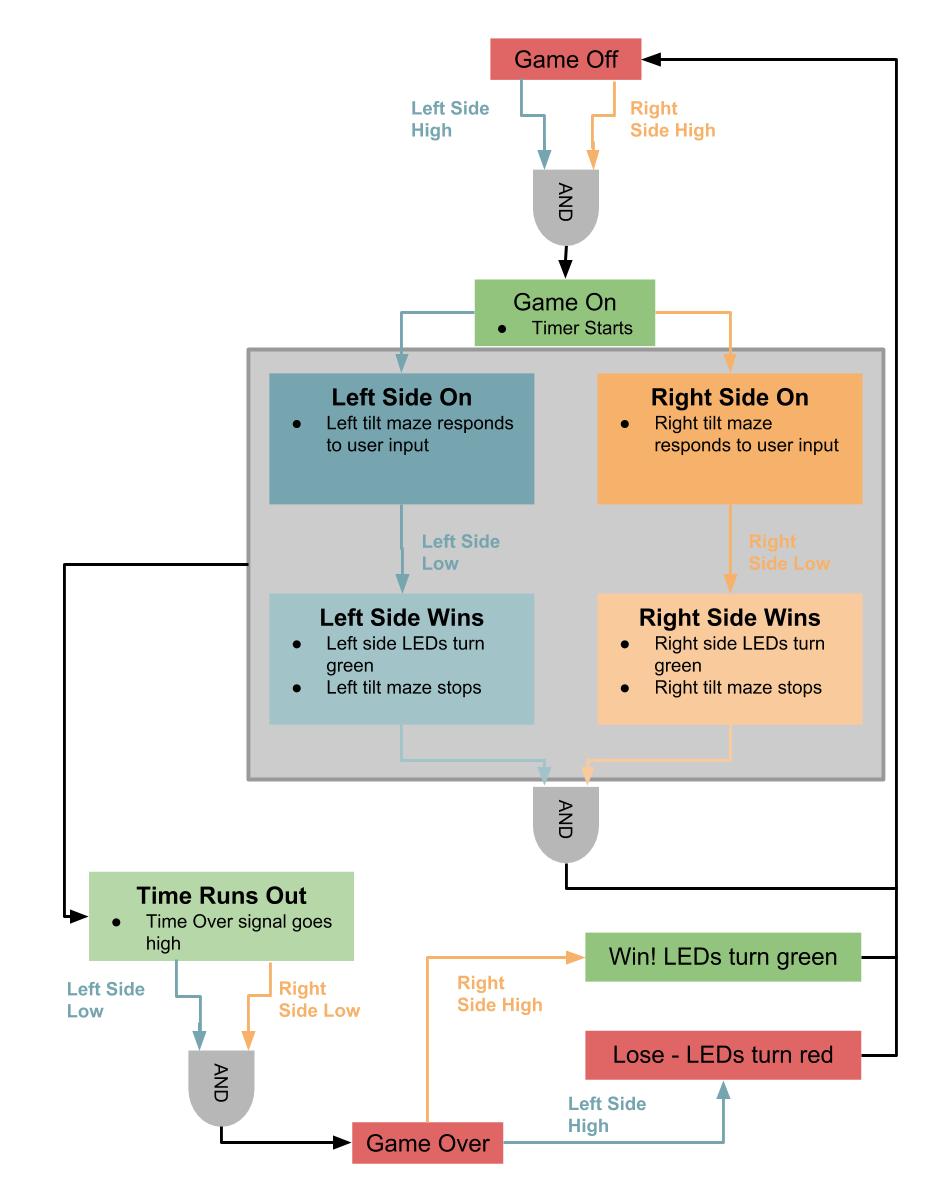
The Arduino
The two joysticks used to control the tilt mazes and the countdown communicate via I2C. We decided to use an Arduino to communicate with those devices because Arduino has a built in library for I2C communication. Because the joysticks control the four servos for the two tilt mazes, we decided to also control those for servos with the Arduino. The Arduino communicates with the start stop microcontroller via three lines. Two of those lines are output signals from the microcontroller that tell the Arduino which sides of the game are currently on, and the third is an output signal from the Arudino that signals to the microcontroller when time has run out. The time over pin remains low throughout the entire game until the countdown timer runs out, at which point it goes high to signal to the start stop microcontroller to start shutting the game off.
The Arduino starts with everything off including the LEDs. When both the right and left input pins go high, the Arduino turns on both the right and left tilt mazes. If at any point, the right or the left input go low before time has run out, it means that side has won, so the Aruduino turns off that side and changes the LEDs on that side to green. If both sides win, the entire strip of LEDs turns green and the Arduino returns to everything being off. If time runs out, the right and left side continue to function until the right and left signals go low. When both of them have gone low, the game is over. Once the game is over, if the right pin goes high, the Arduino turns the LED strip green to indicate that the players have won, and if the left signal pin goes high, the Arduino turns the LED strip red to indicate that the players have lost.