Electrical
Overview
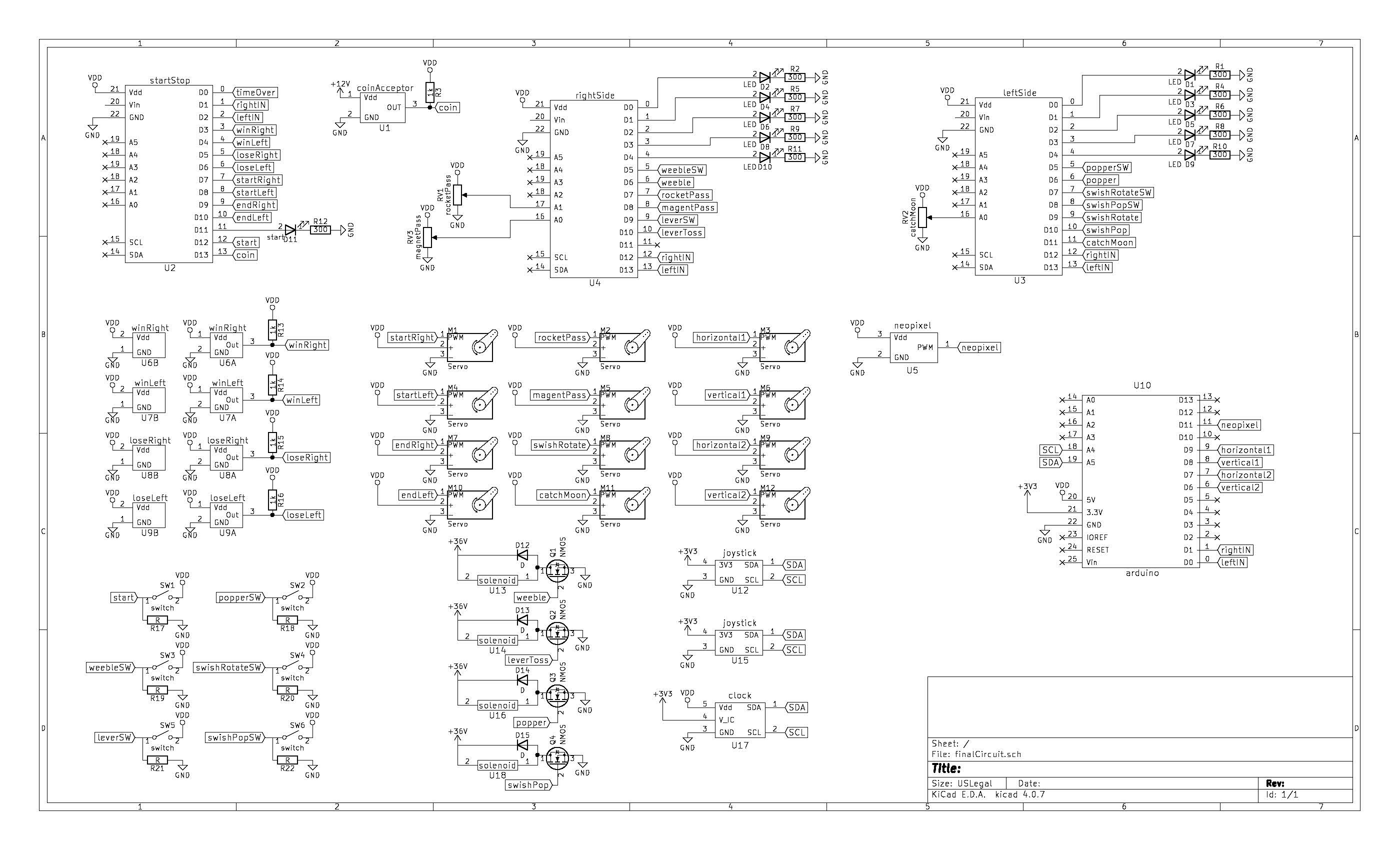
We have a total of sixteen sensors, sixteen motors, three PIC microcontrollers, one Arduino, and two power supplies. A diagram of how everything fits together is below:
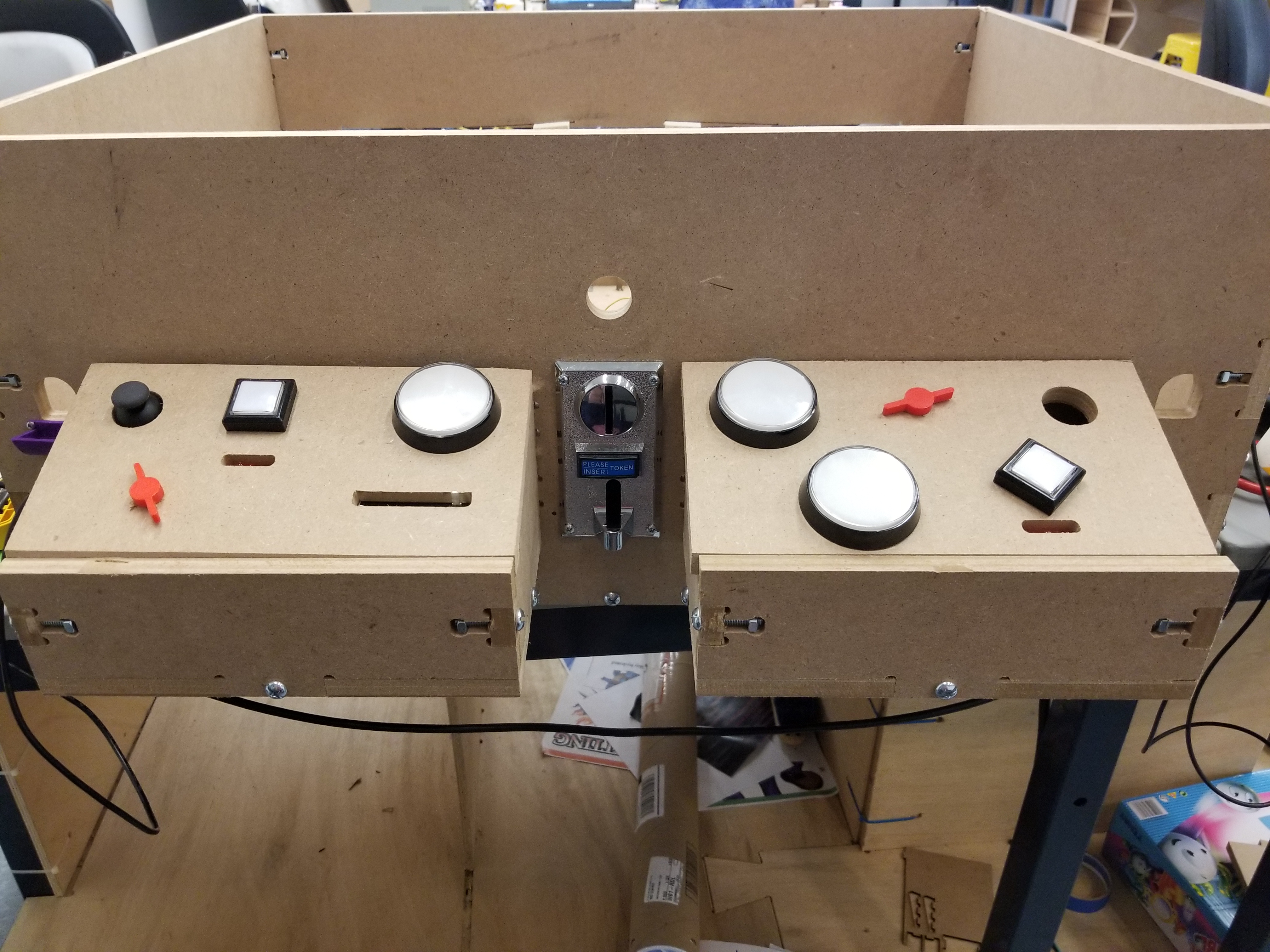
The Controls
Our controls consist of one coin acceptor, six buttons, two potentiometers, one slide potentiometer, two joysticks, and four break beam sensors. The six buttons are all connected to pull down resistors, so the signal pin goes high when the button is pressed. The six buttons control the start, the popper, the lever toss, the swishel swashel rotation, the swishel swashel popping mechanism, and weeble wobble. The two potentiometers and the slide potentiometer output a voltage between 0V and 5V which is then used to control the position of the two sides of the ball pass and the shoot the moon. The two joysticks communicate with the Arduino via I2C and are used to control the two tilt mazes. The four break beam sensors let us know when a ball has gotten to the end goal or when it has fallen into the ramp of failure.
Solenoids
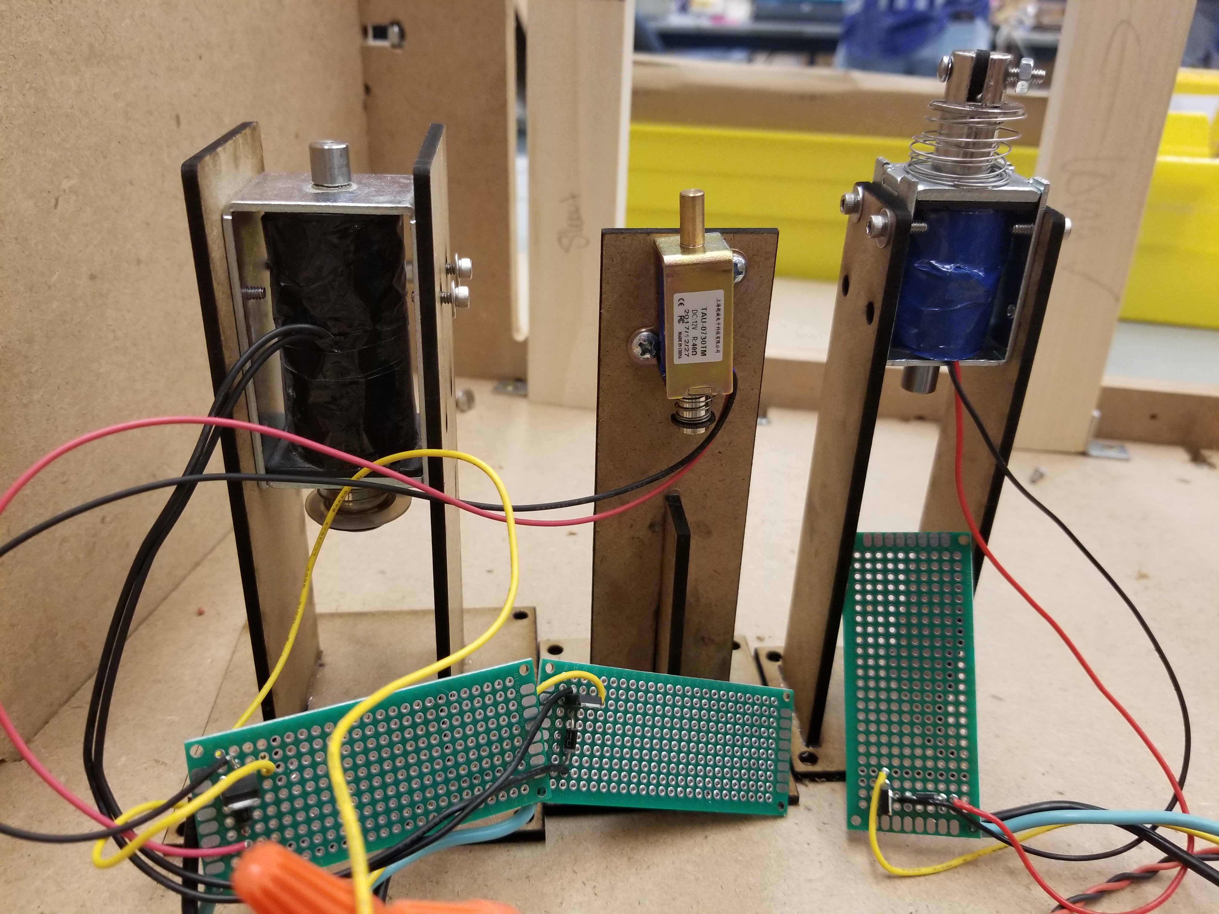
We have three different sizes of solenoids in this project. Two giant ones that run off of 36V, one medium one that runs off of 24V, and a large solenoid that runs off of 12V. Each solenoid is attached to a protoboard with a transistor and a diode. This enables us to vary the voltage on the solenoid by putting a PWM signal on the gate of the transistor at different duty cycles. It also enables us to run all of the solenoids off of our 36V power supply.
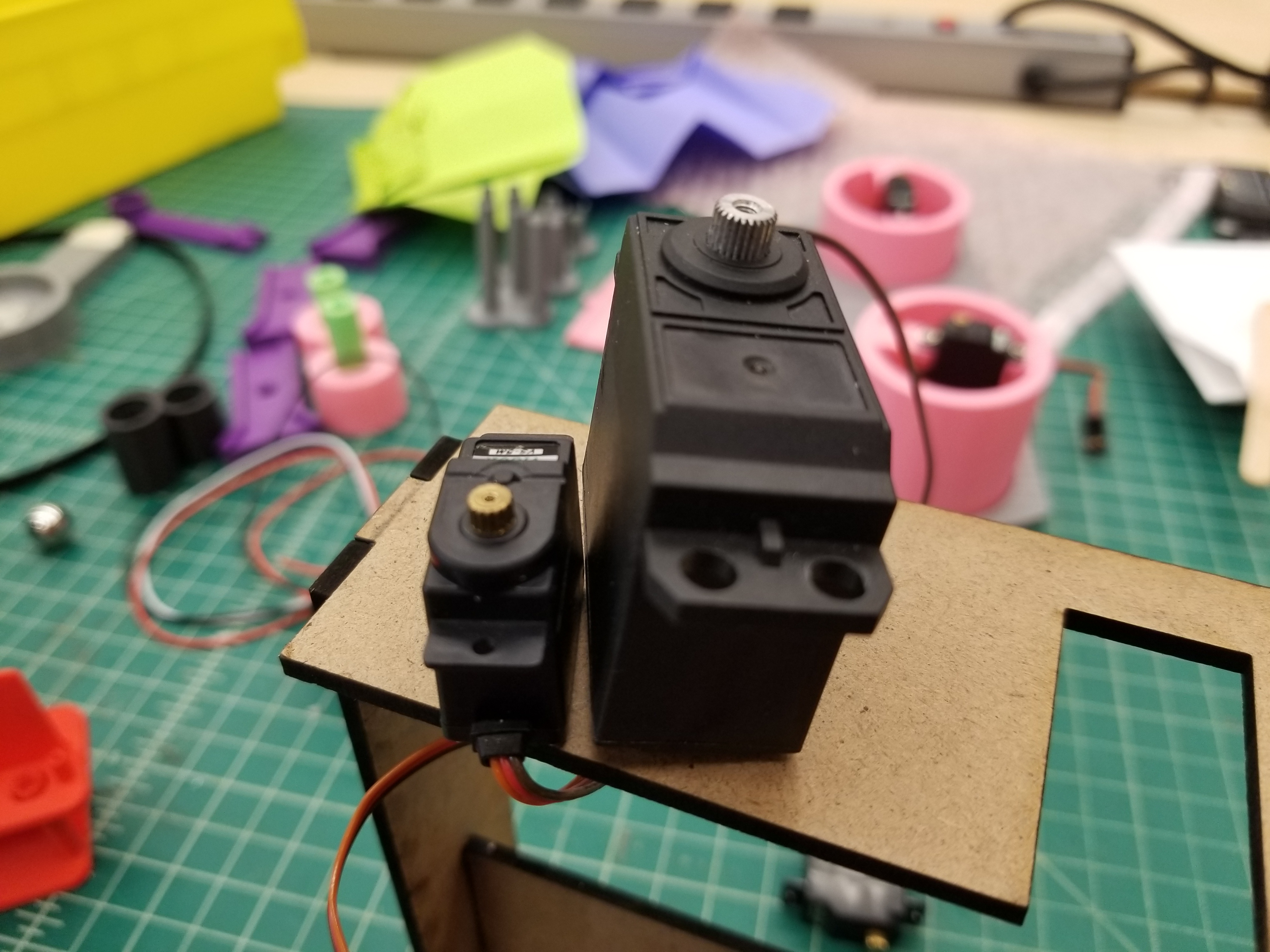
Servos
There are a total of 12 servos in Lunacy. 11 of them are microservos, and 1 he normal sized servo. All of the servos run on 5V, and are powered directly from the power supply rather than through the microcontrollers or the Arduino. We decided to use a larger servo for swishel swashel because they tend to have less jitter than the smaller ones, and we have room in swishel swashel for a larger servo. The PWM cables on the four servos that control the two tilt mazes are connected directly to the Arduino, and all other PWM cables connect to one of the three microcontrollers.
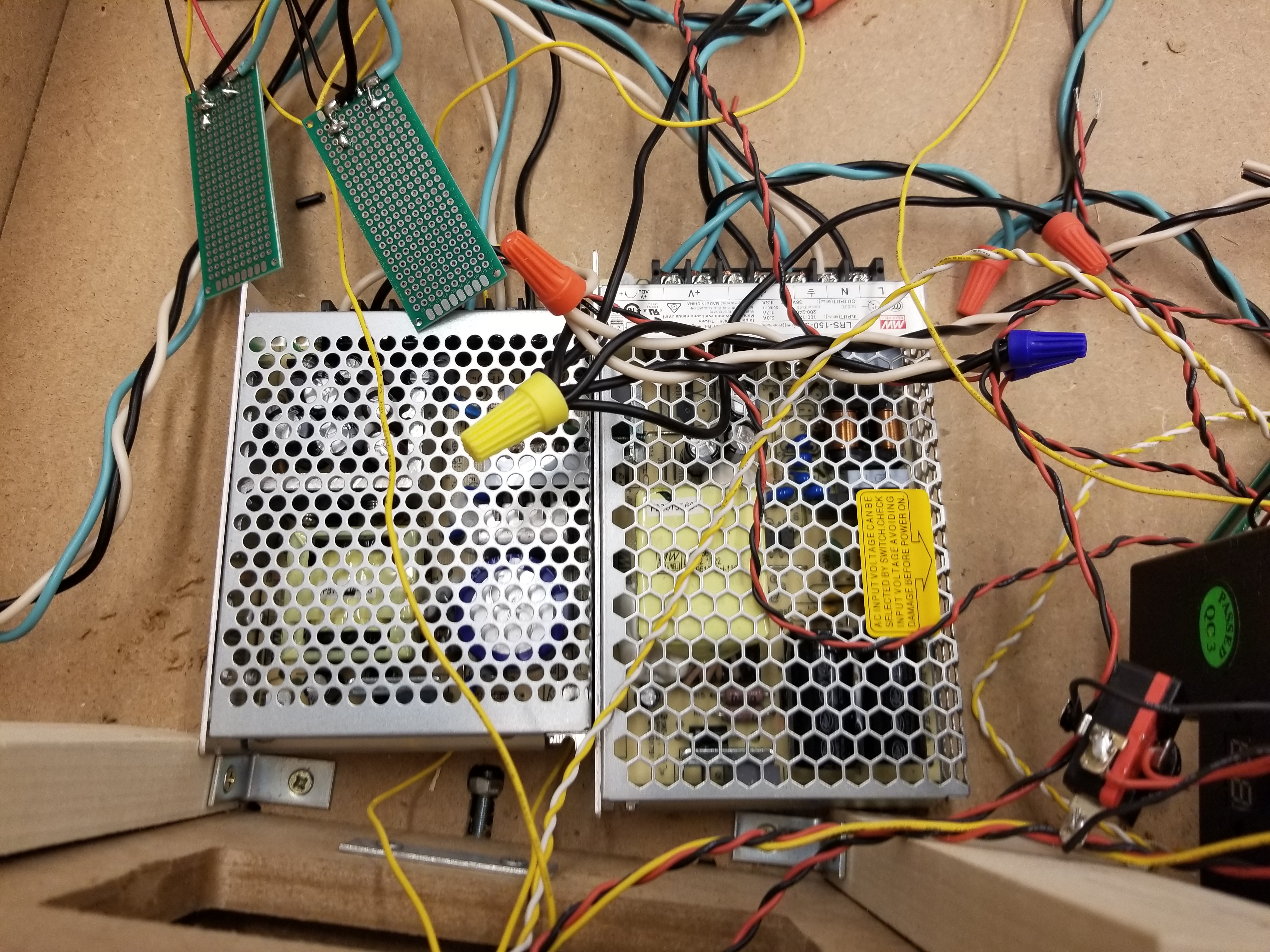
Power
Powering this entire system created a large challenge. All of the servos and micrcontrollers have to run off of 5V, the coin acceptor has to run off of 12V, and the solenoids have to run off 12V to 36V. We could not find a single power supply that could provide enough current at those 5V, 12V, and 36V, so we decided to split up our power circuitry into two power supplies: one that can supply 5V and 12V, and one that can supply 36V. The servos, microcontrollers, Neopixels, and Arudino are all powered from the 5V supply, the coin acceptor is powered from the 12V supply, and the solenoids are all powered from the 36V supply. In total with all of our devices, we needed about 5.8 Amps at 5V, 0.5 Amps at 12V, and about 3.2 Amps at 36V.
The two power supplies attach to a power port via screw terminals and splay connectors, and from there, the box is directly plugged into a wall outlet. Each solenoid has its own 16 gauge connection to the 36V power supply. There are two 16 gauge cables running from the 5V supply which then each connect to multiple 24 gauge wires to power everything that needs 5V each microcontoller and servo has its own 24 gauge power supply. The coin acceptor has its own 24 gauge cables running directly from the 12V supply. The grounds of all of the supplies are connected to ensure correct voltage levels.