Firmware
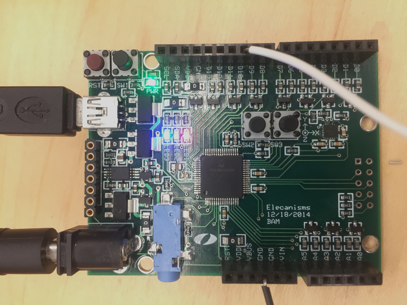
Software programmed on a hardware device: PIC24 Microcontroller.
Diagram
Shift Registers
For Blackout to be successful, we needed our microcontroller to read inputs from 32 buttons and write outputs to set 32 lights to be on and off. This would be simple if the microcontroller had 64 digital I/O pins to spare, but we needed another solution. This is where the shift registers came in. Using 4 shift registers, we were able to consolidate those 64 I/O pins into just 8: 1 for the clock, 1 for the reset, 2 for the data (MOSI and MISO) and 4 chip select pins, one for each shift register.
SPI Communication
readRegisters() writeRegisters()
To use our shift registers, we are communicating over SPI (Serial Peripheral Interface bus) serial communication. This requires sending and receiving a couple data transfers each time we want to do something. This lets the device know we are communicating with it and whether we are about to send or receive data.
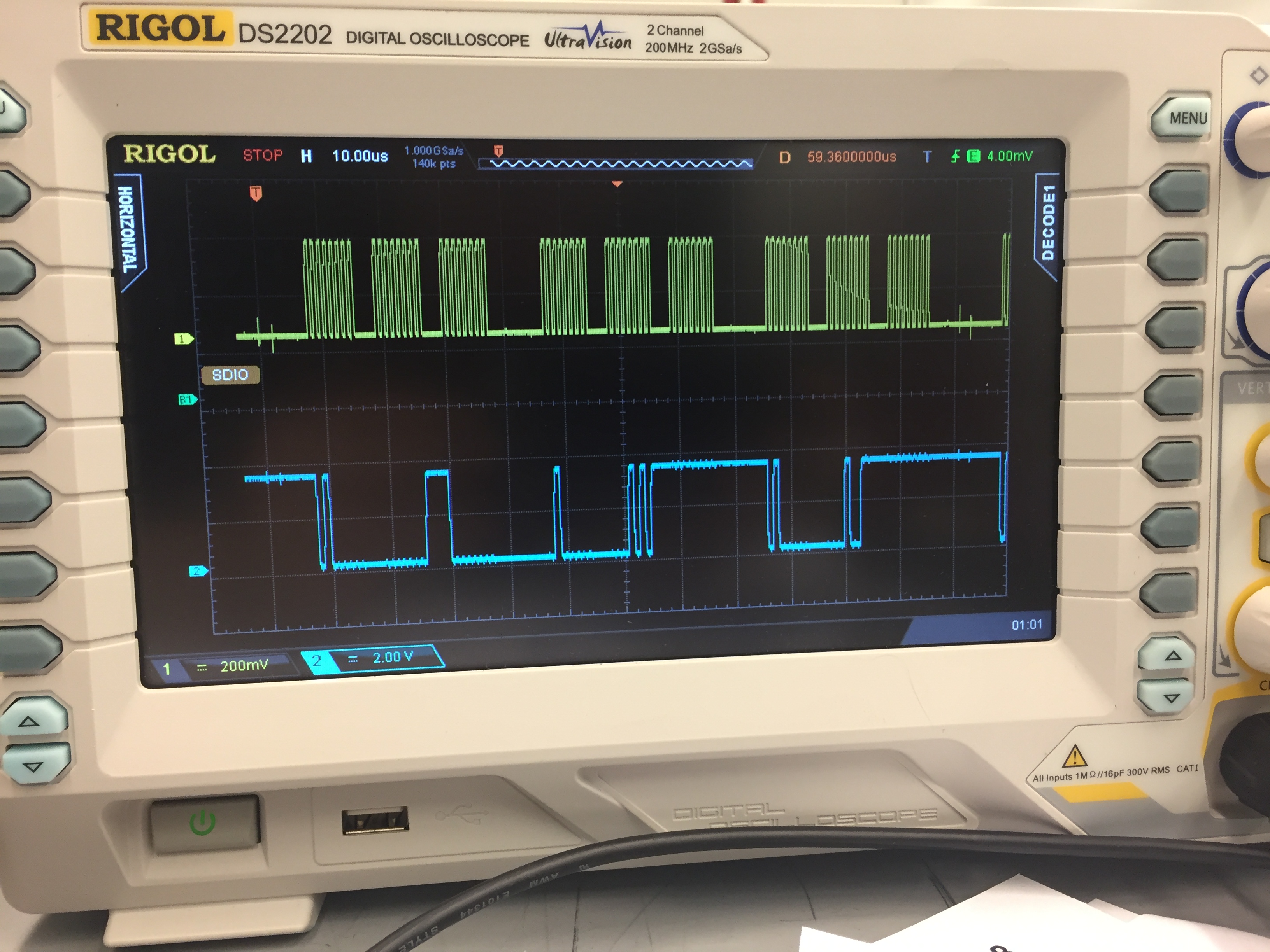
The image above shows data being read from the oscilloscope to see whether the data transfers are happening as expected. The yellow line shows the clock pulses, and the blue shows the data switching between high and low as the clock pulses. This was really interesting, because we were actually able to see the bits of data we were sending in these scope readings. (Wow!) This also proved to be extremely useful in debugging any communication issues, since we were able to actually see exactly what was being sent.
Toggling Partner's Lights
playGame()
There was some fun binary logic that went into taking the button values read from a shift register to determine what binary binary value should be written to the corresponding light shift register. We were able to read and write these 1 byte (8 bits) at a time. After reading a new value a bitwise XOR between that value and the previous value will give the difference between the values. Then, a bitwise AND between this difference and the value that was just read results in an 8 bit value representing which bits were rising. XOR the value where the rising bits are high and all others are low with the current 8 bit value of the corresponding lights shift register to get the new lights value. Following this process, the buttons will always toggle the appropriate lights.
Lights Randomly Turning on
LightsRandom()
To make the lights randomly turn on as part of the gameplay, every timer period (about 1 second) a random number between 0 and 3 is selected to decide which set of 8 buttons will be written to. Next, a random number between 0 and 7 is selected, and a 1 is shifted that many bits into the 8 bit lights value being written to those 8 lights. This makes a random light on either panel turn on, but will not cause any lights to turn off.
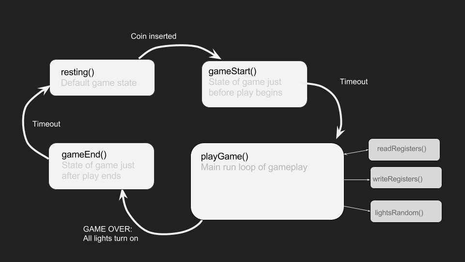
Coin Mech and the Game Start State
CoinCheck() GameStart()
As part of our “minimum viable game”, we wanted to include a coin mech that accepts pennies to start the game. On the firmware sidem the coin mech is a “pull-down” system, so a single dip in the signal output triggers the game to start. In the main loop, it is always checking whether the coin mech pin is low. Once it is, the game start code is triggered. The lights illuminate row by row to prepare the player, then they all switch off and the game begins.
Tickets and the Game End State
GameEnd()
The end condition of the game is when all lights are on on either side. During the game, tickets are spewing out of the top of the enclosure at a constant rate. This means that the longer a player lasts in the game, the better they do and the more tickets they can win! Once the game is over, all lights flash to let the player know the game has ended, and the tickets stop.
Repository
You can see all of our firmware code and more on our Github repo!
