Electrical
The electrical system of the game.
Wiring
With the 32 button lights in our system, we very quickly realized the importance of strong wiring management. In our final game, a plan was made for exactly how long each wire should be to connect to the protoboards and be as neat as possible. Rails shared between buttons were daisy chained together, and the wires coming off of the buttons towards the protoboards were neatly twisted. Planning this all out in advance was extremely valuable.
Wiring Plan
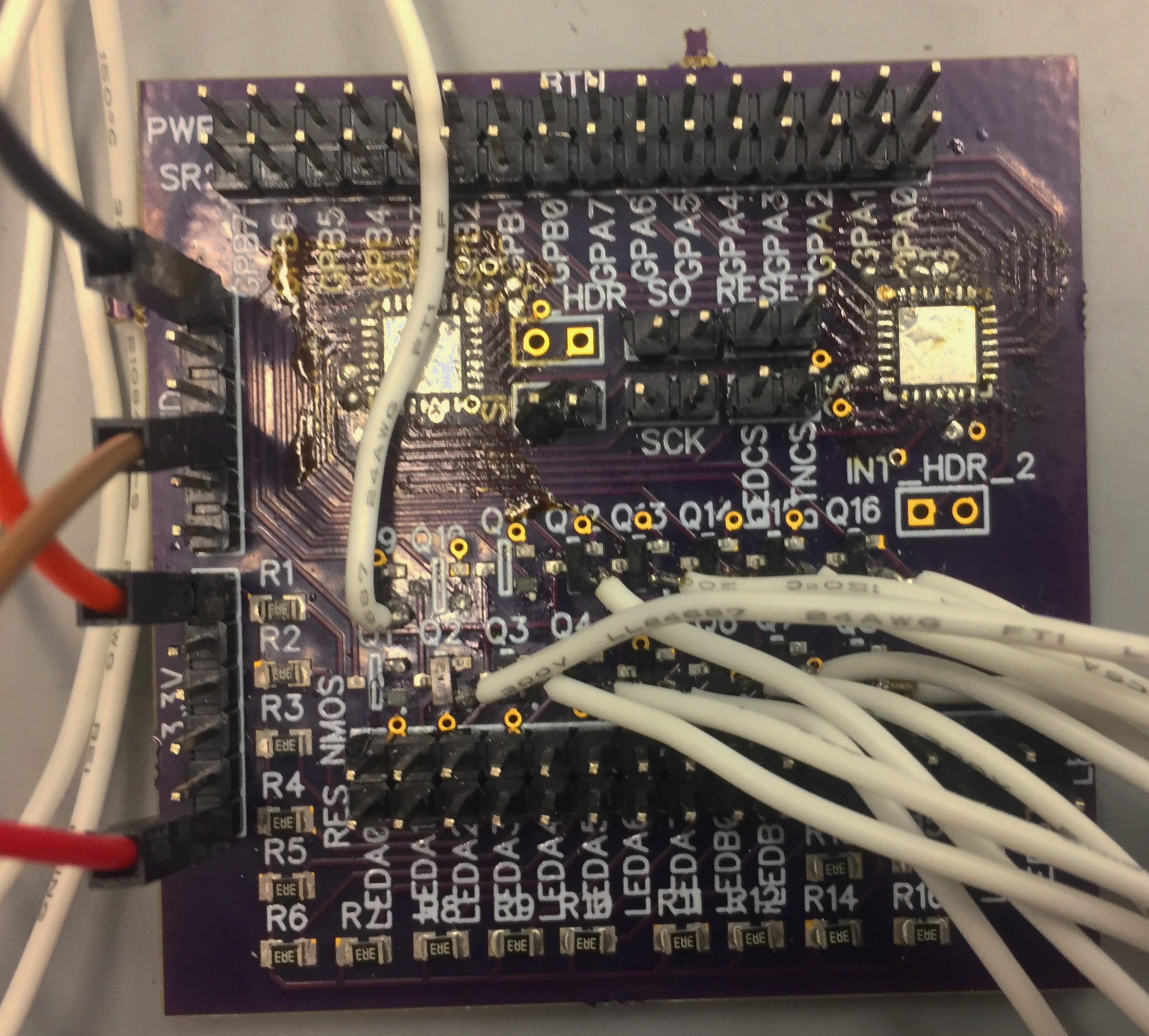
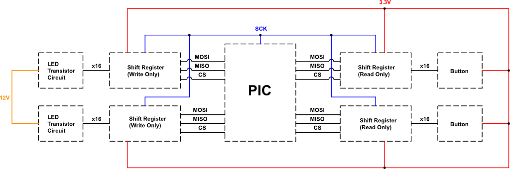
- - Each panel has an identical protoboard that is supplied with 3.3V from the PIC. The implementation of shift registers decreases the amount and length of wires needing to plug into the PIC; 64 pins (a button press signal and LED on signal for each button) to 8 pins. We currently have one chip select for each shift register (two from each board for a total of four), and four other signals that are tied together from board to board (RESET, CLK, MOSI, and MISO).
- - Red wires - 3.3V power for button part - daisy chained together to form a rail powered from the PCB
- - White wires - digital output from button to indicate it’s been pressed - goes to input of shift register circuit
- - Yellow wires - power supply to LED
- - Black wires - ground supply to LED and button
- - For each button, the yellow and black wire are joined together for ease of plugging into PCB header pins and the white, yellow, and black wire are twisted together.
- - The three-wire twist for each button is placed along the bottom of its row of buttons from the button to the left side of the panel and then downward along the edge to the PCB.
- - Button naming scheme by panel, shift register side, and shift register row: P0, P1 / A0 - A3, A4 - A7, B0 - B3, B4 - B7