Firmware Backend
The code that controls the game modules and communicates between the master module and the individual puzzles
I2C Library
In order to move data between our PIC microcontrollers we used the onboard I2C peripherals to create an I2C bus. We selected I2C because it is designed to be used in a multiple-device bus with a built-in addressing scheme. This would allow us to easily develop modular puzzles that could be dynamically reconfigured during use. In addition, may of the accessory devices such as LCD displays and I/O extender LED devices that we had access to required I2C communication. We implemented a standard 7-bit addressing scheme and used a 5V logic level I2C bus with pull-up resistors inside the bomb backplane which allowed for the minimal number of connections to go in each of our connectors.
For certain of our I2C peripheral devices, the I2C peripherals required a level-shifter to 5V I/O in order to reliably communicate. For this, we were able to make simple level shifters with individual FETs and two pull-up resistors per I2C line.I2C application layer
Once we had developed reliable I2C communication, we needed to use it to exchange data on strikes, completion, etc. between all of the peripheral puzzle modules and the master module. To keep I2C bus roles (master/slave) consistent, we decided on a single-master bus configuration wherein the master module keeps track of the game state and polls state updates from all of the peripheral modules and then propagates that state out to all of the other peripheral modules. In order to do this we developed a core I2C reception/response state machine that was included in each of our peripheral modules' source code. We also developed an initialization and data transfer protocol that the master module would run through to keep all of the peripherals in sync with the master game state.
Peripheral Template
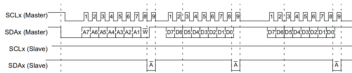
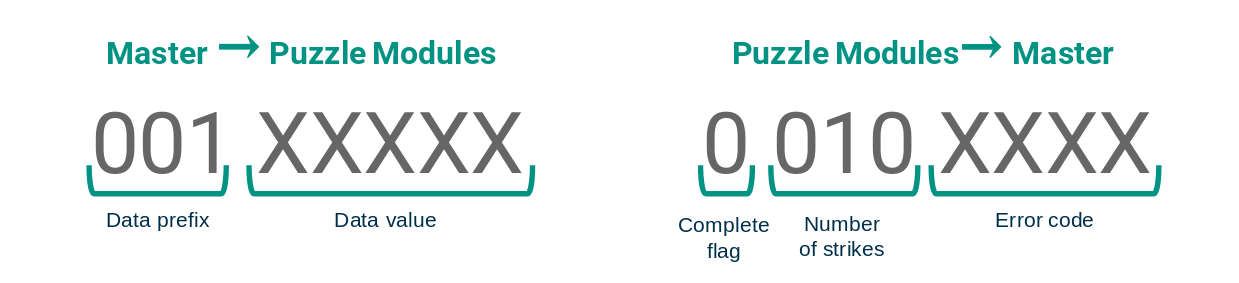
The peripheral template uses an I2C-triggered interrupt handler to process incoming data on the I2C bus. If a module's address is the one being sent from the master, the module either proceeds into a state where it receives a data byte and processes it based on the three most-significant bits as a header, or it proceeds into a state where it responds to the master with a byte composed of its completion state, its number of strikes, and any errors that may have occurred.
The peripheral template also includes five basic states that all of the peripherals have: Startup, Run, Solved, End Win and End Fail. Transitions betweent these are implemented in individual modules based on stimulus from the Master module or game interactions.
Master Procedure
The master module keeps track of the overall state of the game, and so it must manage all of the peripheral PIC microcontrollers' state machines that are running the individual puzzles. On startup, all of the peripheral puzzle modules are in their Startup state, and the Master module polls all of the known I2C addresses of modules to see which modules are connected this round. Once it knows which modules are present, it only interacts with these modules to save I2C bus traffic.
Once the master module knows which peripheral modules are present, it transmits its randomly-generated serial number and the status of its LEDs so the other puzzles can initialize their game states, and then it transmits a game start message to all of the modules. Once all of the modules are running, the master module begins continuously polling all of the modules sequentially and gets back completion status, number of strikes, and error codes. If strikes are detected, the master then sends the new strike total out to all of the modules.
If the number of strikes is greater than two or the timer runs out, then the master module sends out a game end message to all of the connected peripherals and they move themselves into their End Fail state. If the master module receives a complete message from all of the connected modules, the master transmits a game end message that puts the peripherals in End Win state. In this way, the peripherals act as views and controllers to the model that is contained within the master module firmware, to use an MVC analogy.
Finite State Machines
All of the peripheral game state machines are implemented using a function-pointer implementation of a finite state machine. This implementation sets up the program execution while loop to constantly evaluate the function pointer state. By setting the function pointer to different handler functions, the finite state machine's behavior can be neatly separated into well-encapsulated independent functions. In the following code example, an example of a main loop calls a state handler function that is defined above it, and an example bare state handler function is shown. For some game modules, it was prudent to have sub-fsms that handled certain phases of gameplay within the Run state.
Code Example
typedef void (*STATE_HANDLER_T)(void); //Function pointer to state handler

// forward declaration of module modes
void setup(void);
void run(void);
void solved(void);
void end_win(void);
void end_fail(void);

STATE_HANDLER_T state, last_state;

int16_t main(void) {
	//Setup code here

    state = setup;

    while (1) {
        state();
    }
}

// STATE MACHINE FUNCTIONS /////////////////////////////////////////////////////

void setup(void) { // Waits for master module to start the game
    // State Setup
    if (state != last_state) {
        last_state = state;
        // setup state here
    }

    // Perform state tasks

    //Check for state transitions
    if ((start_flag == 1) || (SW2 == 0)){
        state = run;
    }

    // State Cleanup
    if (state != last_state) {
        // cleanup state here
    }
}