
We have undergone many iterations throughout the semester.Let us show you all the intermediaries!
Forewords
Our project was divided into four phases, each of them called Sprints. At each of these sprints, with the exception of Sprint 2, we had an iteratively improved integrated prototype that could be play-tested. It was exciting to see, at the end of each sprints, how much we have come from the beginning!
Sprint 1
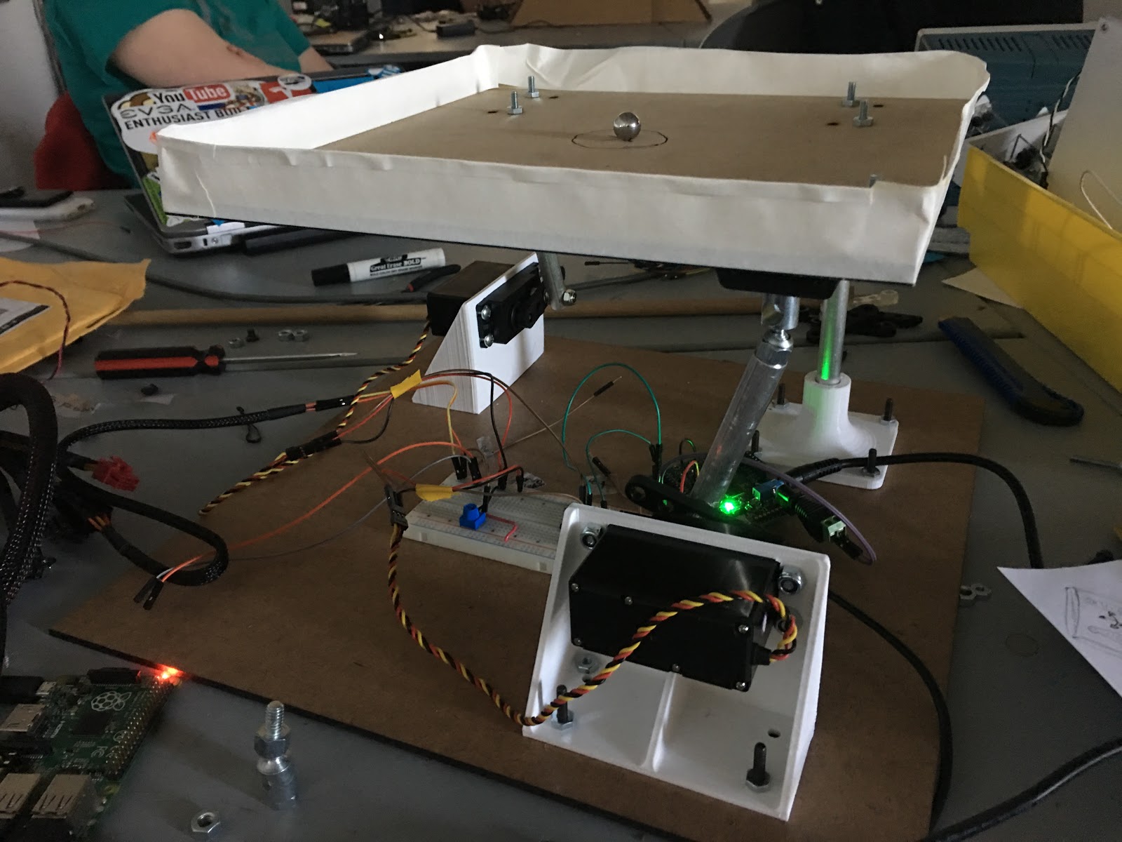
At the end of Sprint 1, we had a small-scale board designed and built. The
aims of Sprint 1 were to, connect with the RasPi to communicate with the
Wii balance board, and to design and test our initial mechatronic
system for the tilt mechanism.
Mechanically, the biggest insight of this sprint was with the ball joints used in mounting
the tilting board to the base. We were using ball joints for all 3 connections, and this
left an extra degree of freedom allowing the tilting board to spin rather than purely tilt.
This made us realize we needed to use a U-joint in the center mount to prevent the rotation.
Electrically, the challenge was to give the servos 5V, when the signal from the PIC was only
3.3V. We developed the logic converters shown in the Electrical
Design section during this sprint.
Sprint 2
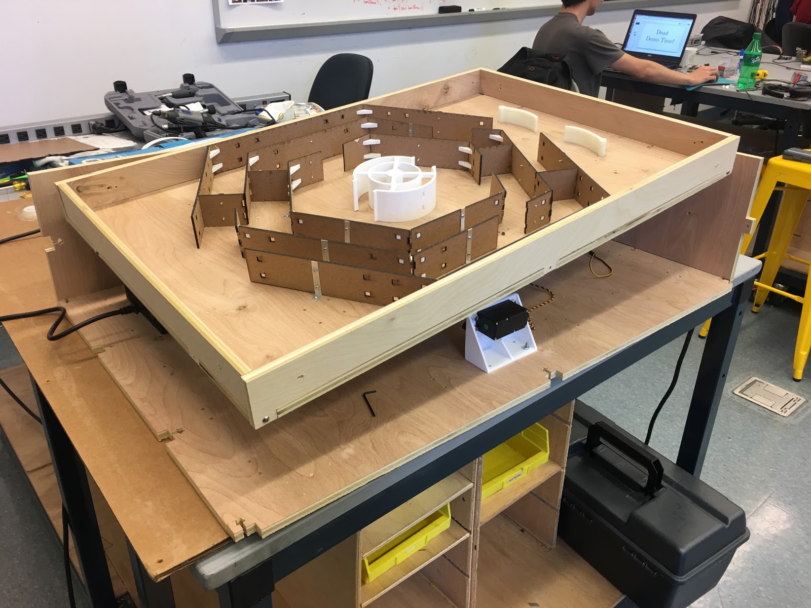
Sprint 2 was a lot of experimentation and growth. By the end of this sprint, we had defined
our MVP, built a full-scale model of the game, and had tested
several actuation and data collection methods.
During the sprint, we Shopbotted our first life-sized hull; due to
lack of foresight and changing designs, the panels had to be postprocessed nonetheless to
accomodate our central maze and the spinner.
We also implemented our initial layout of the FSM, with which we could control flippers and
the central spinner. We also had the coin mechanism working, and mostly accomplished lots of
tasks in the way. A lot of work was spent on debugging; the linear actuator was
malfunctioning, for instance, as well as the accelerometer library. After a period of
efforts in vain, we prioritized on the integrated product, so both of these efforts were
tabled.
Overall, we determined our MVP and were well on our way to making a complete game.
Sprint 3
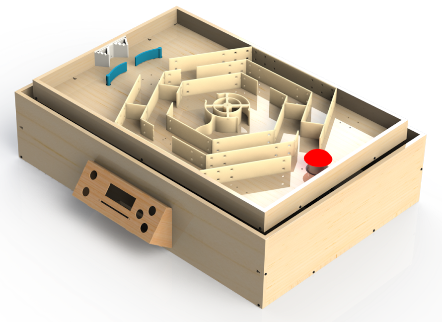
This sprint marked our Minimum Viable Game.
Mechanically, we successfully made the game
robust with a U-joint designed for a car steering rack. This prevented twisting and made it
substantially less likely that an errant 4th grader would damage the system. We additionally
solved our issues with the center spinner clearance that we were having in Sprint 2 by
increasing the gap between the walls to allow the ball to easily travel between them,
lengthening the connection to prevent interference between the walls and the game surface,
and integrating the blocking outcrop into our 3D printed part, rather than having a wood
flap that fell off during testing.
Electrically, we wired improved the strength of the electromagnets by using
a boost
converter to step up the 12V power supply potential to 30V. However, we were actuating this
signal directly with a simple push-button. Moving forward, we would need to use mosfets to
electronically control the actuation of the electromagnets This allowed us to design the
electrical system, even without being integrated in the code yet. We tested the pop bumper,
so that we could integrate it in the next sprint, and wired up buttons for control as well,
and started planning for moving our circuit to proto-boards.
For Software, we updated the state machine to be easily extensible (this
turned out to be
extremely helpful later on), and had all the game logic and active element control
implemented and tested. This was also the sprint where we got the LCD screen with
instructions working.
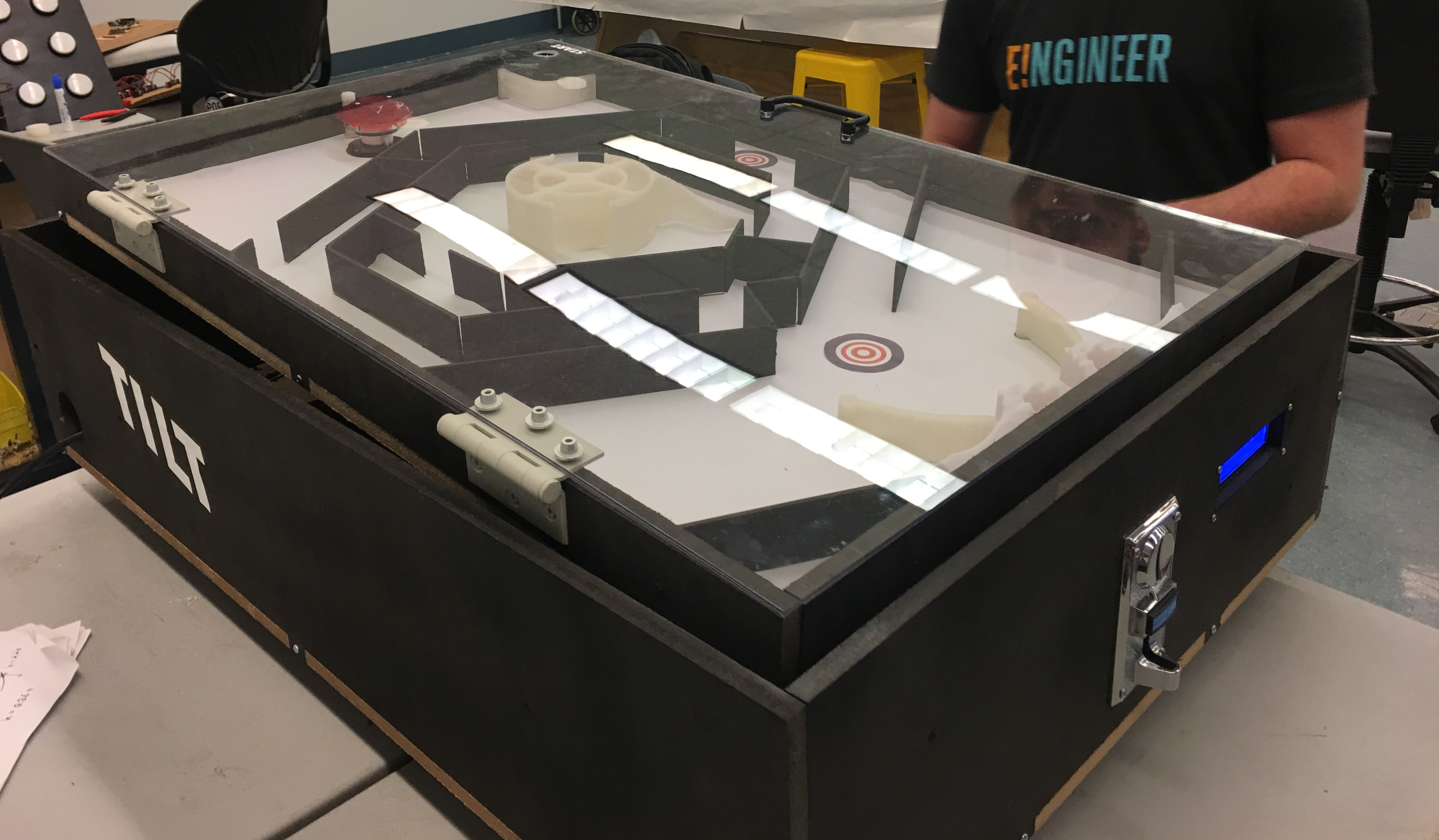
Sprint 4
The final 2 weeks of our project were mostly dedicated to polish and
robustness. We improved
electrical connections, worked out software bugs, recut panels, painted the the game, and
more. We took all the design insight we had learned prior and cut an entire set on new body
panels out of MDF. We chose MDF over plywood this time around as it was less subject to warp
(our 1st game area was a little askew).
The hardboard maze was designed to slot directly into the game surface as a press fit rather
than needing to be fastened down by screws, as was the case with the first design. Lastly, a
coat of black paint was applied to all the exposed surfaces and a layer of while vinyl was
used to cover the countersunk screws holding in various components into the game area.
When we revisited the Raspberry Pi, it unexpectedly broke down, so we had to reconfigure
another one. A lot of effort was put into making the startup sequence, as well as the
following execution sequence, robust and reliable, so that the game would be a plug-and-play
experience.
Final Game
After all these sprints, we finally arrived at our final product! Click on the link to get started on the systems overview, starting from mechanical.