
Circuits and Devices
Overview
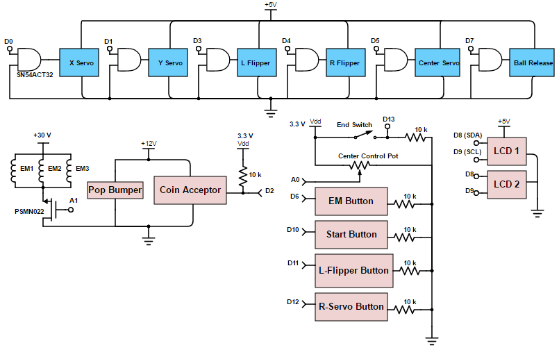
The project incorporates a total of 6 servos, 1 coin acceptor, 1 pop bumper, 3 electromagnets, 4
control buttons, 1 slide potentiometer (0-1 kOhm), two 16x2 LCD displays, and two controllers: a
Pic24 board and a Raspberry Pi. In addition, two patches of copper tape - one connected to ground
and a digital signal pin and the other to a 3.3 V power supply - are arranged such that when the
ball touches both at the same time, a HIGH signal is sent to the digital input. The servos are each
connected to a digital output pin in the Pic24 board (logic conversion explained later). The coin
acceptor and 4 control buttons as well as a switch at the end goal of the game serve as digital
inputs into the pic board, while the potentiometer serves as an analogue input.
The pop bumper functions independent of the control boards: when the ball hits the pop
bumper, it connects a switch that allows a potential difference of 12 V across a solenoid and a 5 V
potential difference across an LED.
Voltage Supplies and Signal
We used an ATX power supply which can provide 3.3 V, 5V, and 12 V to power up all the
electronic components of our game. The servos, the Pic24 board, the Raspberry Pi board, and
LCDs are all connected to a 5 V output. However, since the digital signals from the pic
controller have a high signal at 3.3 V, we use quadruple 2-input positive-or gates
(SN74act32) to make the amplitude conversion between the pic24 board signal and the servos.
The coin acceptor and pop bumper are connected to the 12 V output, while the slide
potentiometer and the signal end of the coin acceptor are tied to 3.3 V. The electromagnets
themselves each need 30 V to induce a strong enough magnetic field so a boost converter is
used to step up the 12 V DC voltage from the ATX power supply to 30 V.
A N-channel 30 V 22 mΩ logic level MOSFET is used to controll the electromagets by
taking an analog signal from the pic board to turn on the magnets for the desired amount of
time. All components share the ground rail connected to the ATX power supply. To insure that
only DC voltage is applied across each component, a 3.3 μF capacitor was placed across each
higher voltage ( 3.3 V, 5 V, 12 V) rail and ground. This grounds higher frequency signals
and noise.
Circuit Design
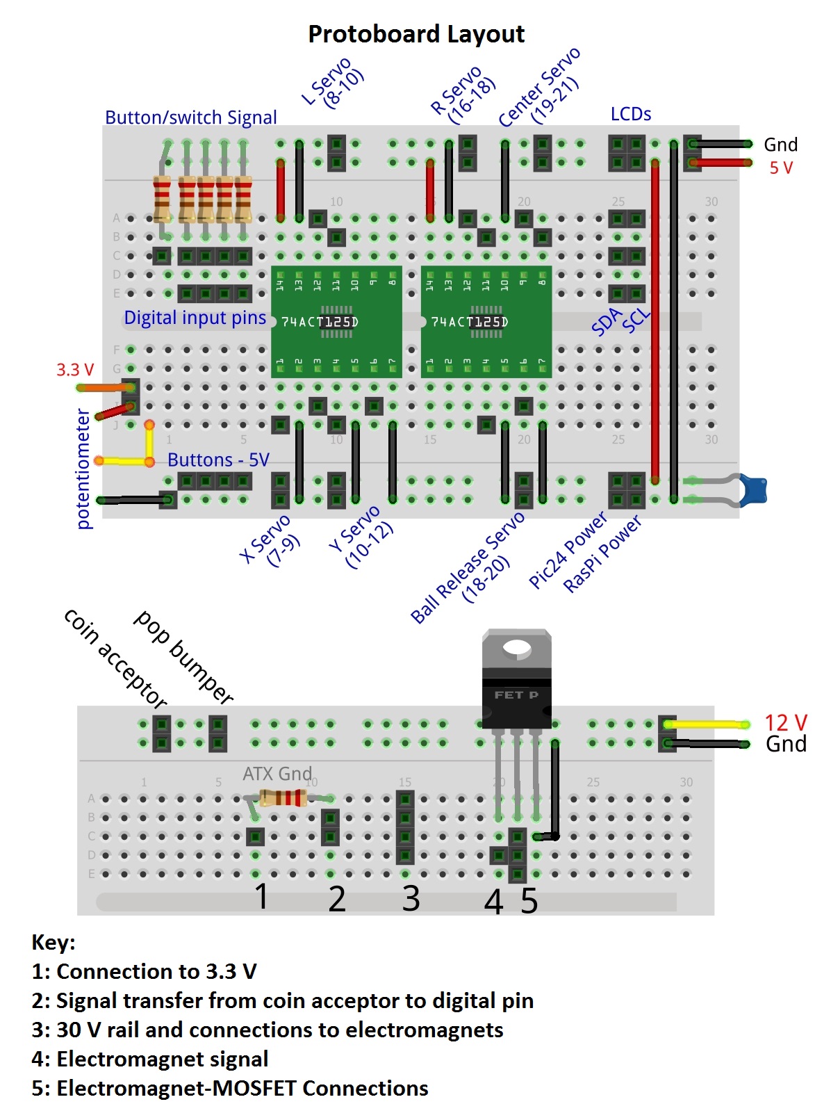
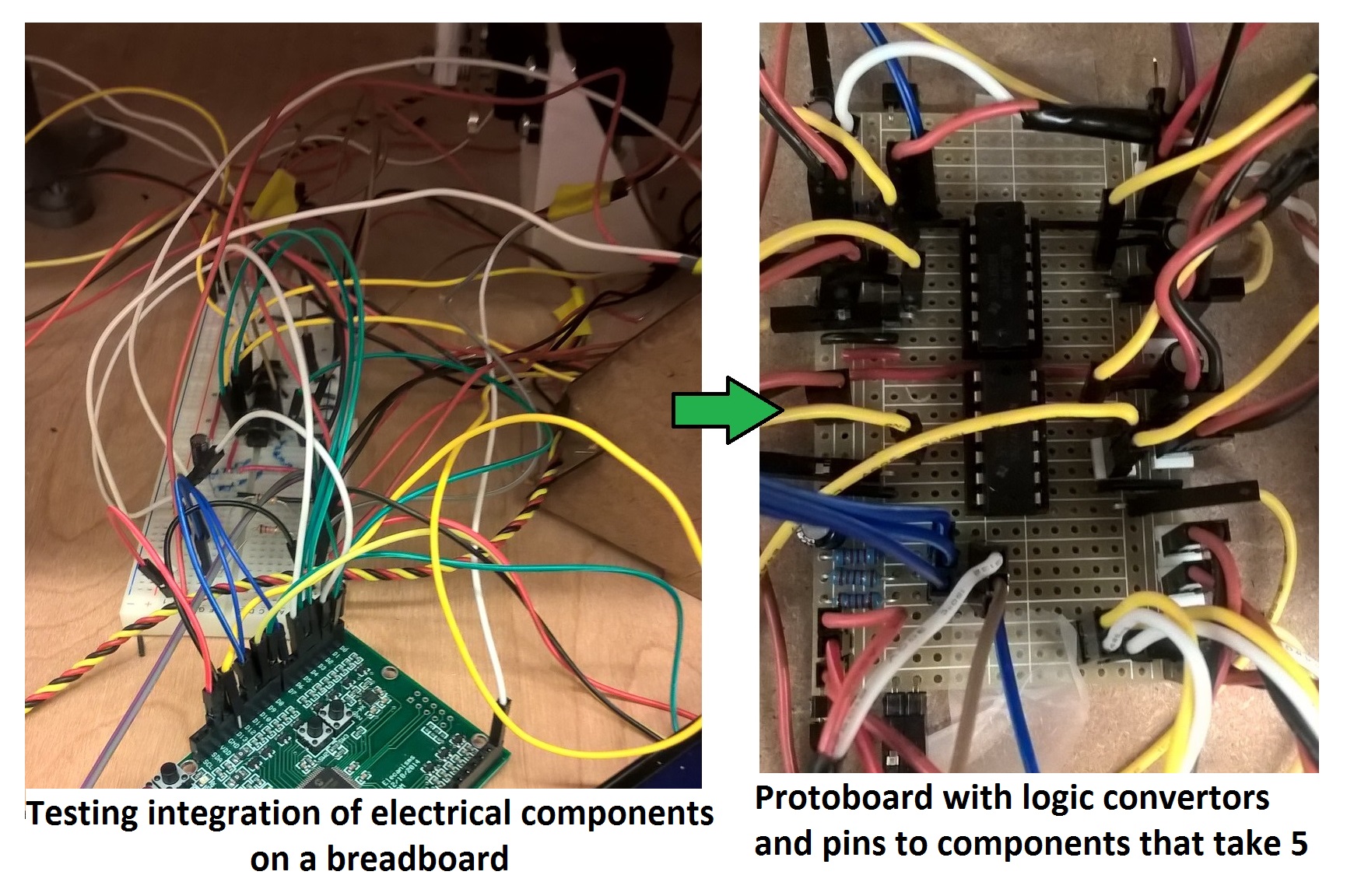
For the first three sprints of the project, we used a breadboard to integrate the electrical components as the project was still evolving. Leading upto the last sprint, we organized the circuit layout and soldered the components (or their corresponding pins) onto a protoboard resembling the circuit layout of a breadboard. We used two protoboards - one containing the components and pins that need 5 V inputs and another containing 12 V and 30 V rails. For consistency all the connections leading to external elements to the board like the controllers, servos, etc. were all soldered as male pins on the protoboard.
Circuit Packaging and Organization
We aimed to make an electrically robust product and easily debuggable. The connections
between the protoboard and the external electrical components were made by
crimping female connectors to color coded wires (red: 5 V, black: ground; yellow:
digital output from Pic24 board and signal to servos; white/blue: digital and analog
inputs). The wires leading to the same components, then, were braided with a drill to
avoid cluttering the protoboard area.
While the electromagnets were still connected through the breadboard, they drew
too much current and caused the breadboard to heat and occasionally malfunction. This is
no longer a problem after the higher voltage 12 V and 30 V components were soldered onto
a separate protoboard.