Mechanical Subsystem
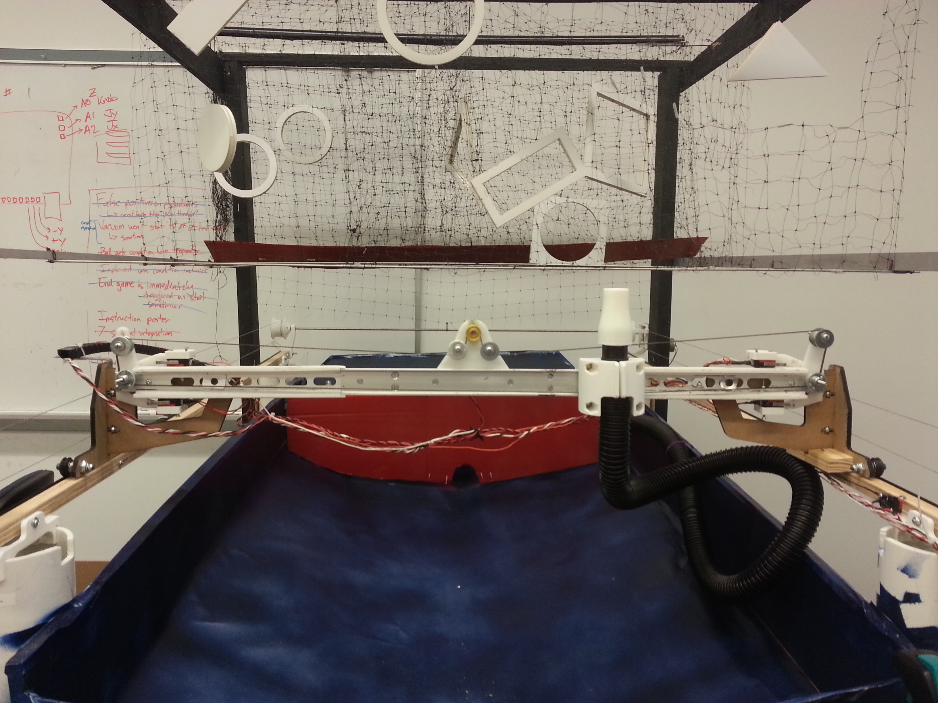
The purpose of the 3D Maze, as discussed more elsewhere, is to support a ping pong ball on a column of air so that a user can steer the ping pong ball in 3D space and pilot the ball through a maze. The mechanical system for the 3D Maze has four essential parts - X axis travel (left/right for the user), Y axis travel (forward/back for the user), Z axis travel (up/down), and finally, the obstacles themselves.
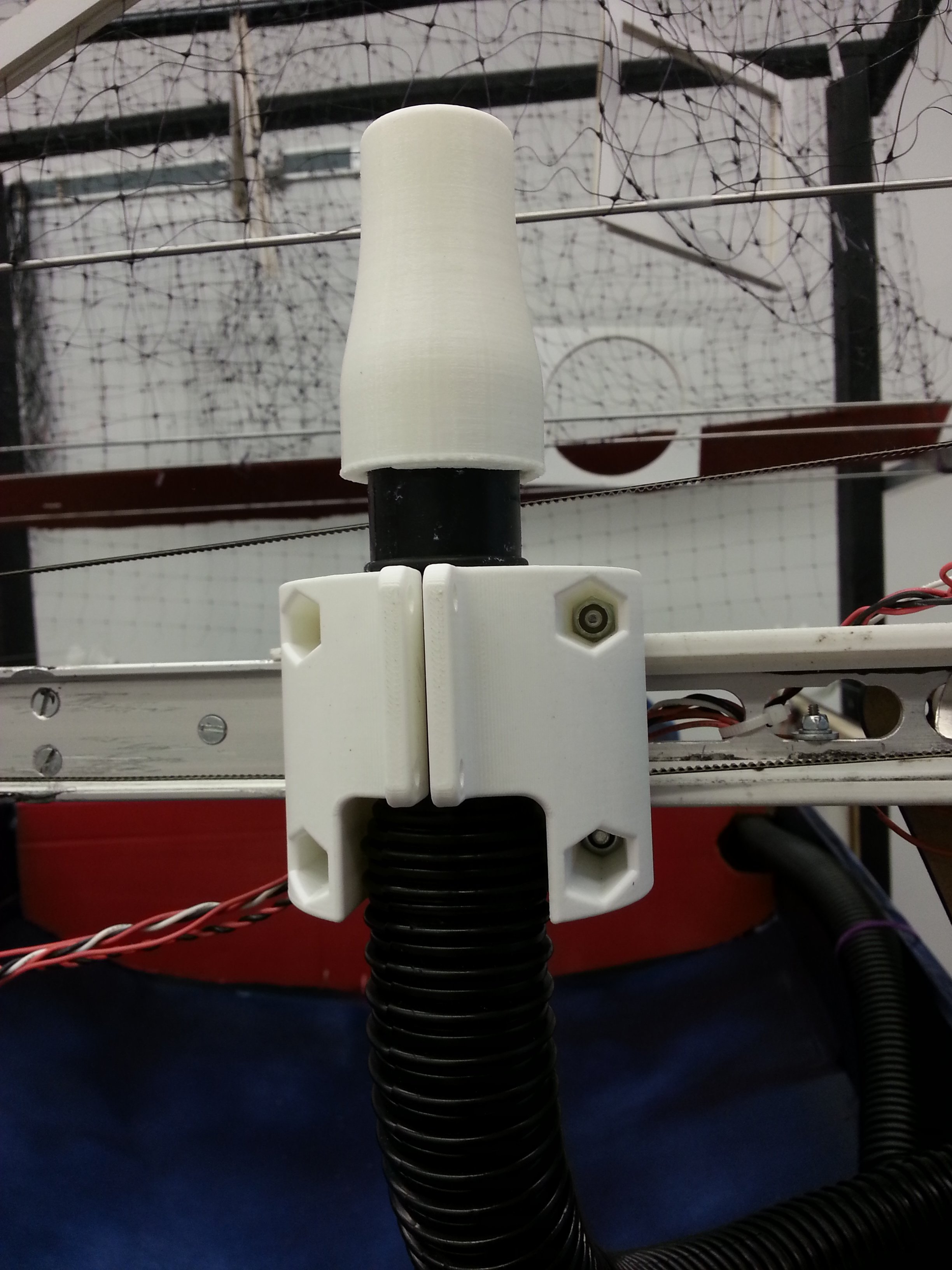
X axis travel is enabled with a C channel tube and cart made to ride in that C channel. The purpose of both the X and Y axes is to support and transport a vacuum tube that blows air to create the stable air column. The flexible vacuum tube is mounted to the X axis cart, which travels along the C channel, driven by a timing belt drive. Limit switches at either end of the C channel provide a safety limit on the system - when the X axis cart hits a limit switch, the software halts all travel in that direction. The C channel found by the team wasn't large enough for the envisioned game, so 3D printed rails were made to form extensions. It was difficult to print the rails cleanly enough to form a precise C channel, and also difficult to position the 3 printed rails accurately enough to form a nice interface to the existing channel, but eventually rails that provided tolerable performance were made.
The X axis drives the cart (and its attached funnel) back and forth along the C rail with a timing belt drive.

3D printed rails form extensions to the existing C rail. The transition from metal to RP plastic was a little sloppy, but served the purpose well enough.

Here the back of the X axis cart can be seen from the back - three wheels ride in the C grooves to form a stable sliding motion.
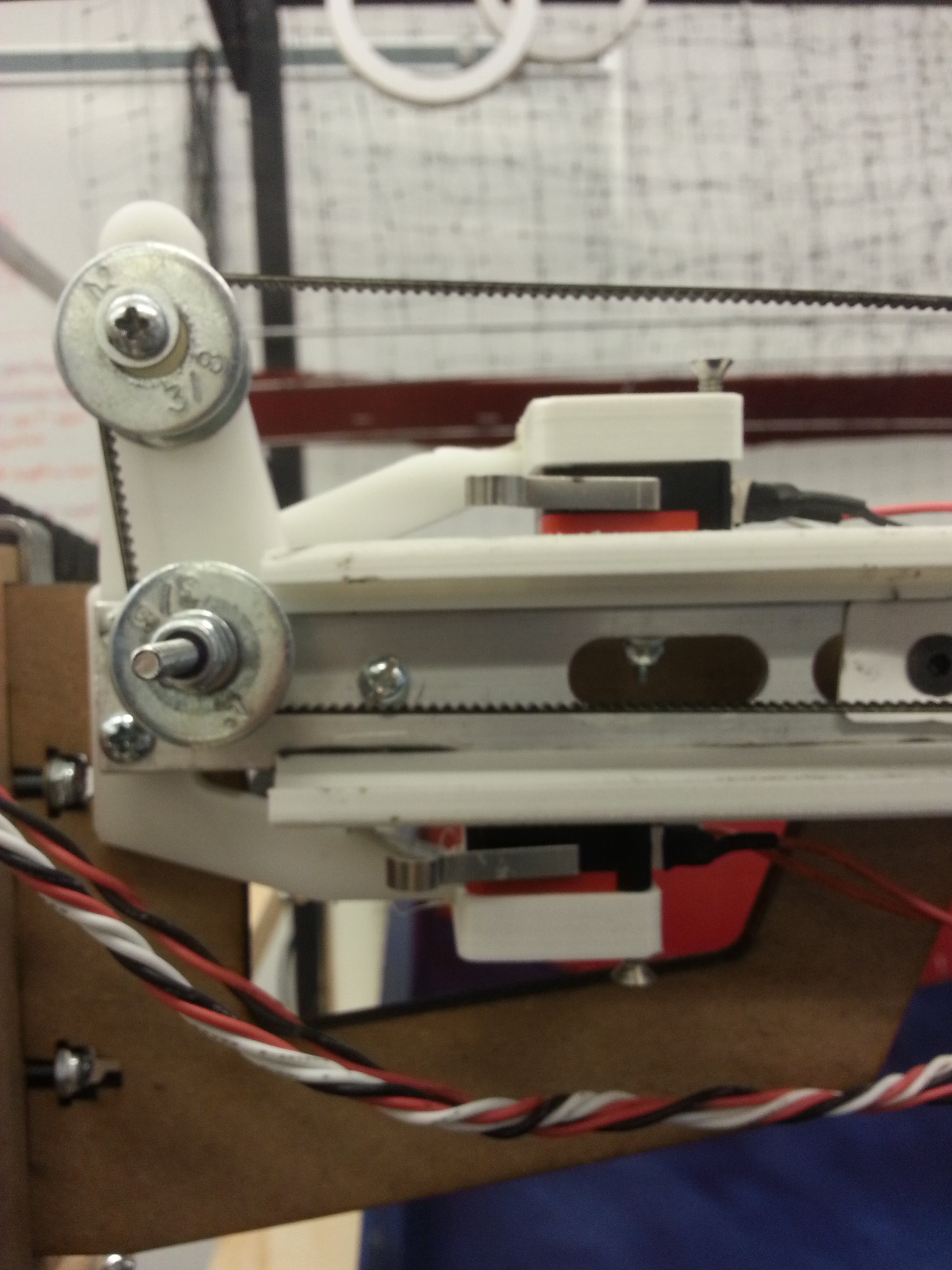
Plastic spacers formed idlers for the timing belt to be routed on, and double X axis limit switches provided 1) a software limit and 2) a physical electrical sutoff in case the software limit failed.

The drive motor transfers torque across the game with a drive shaft, so both sides are driven.
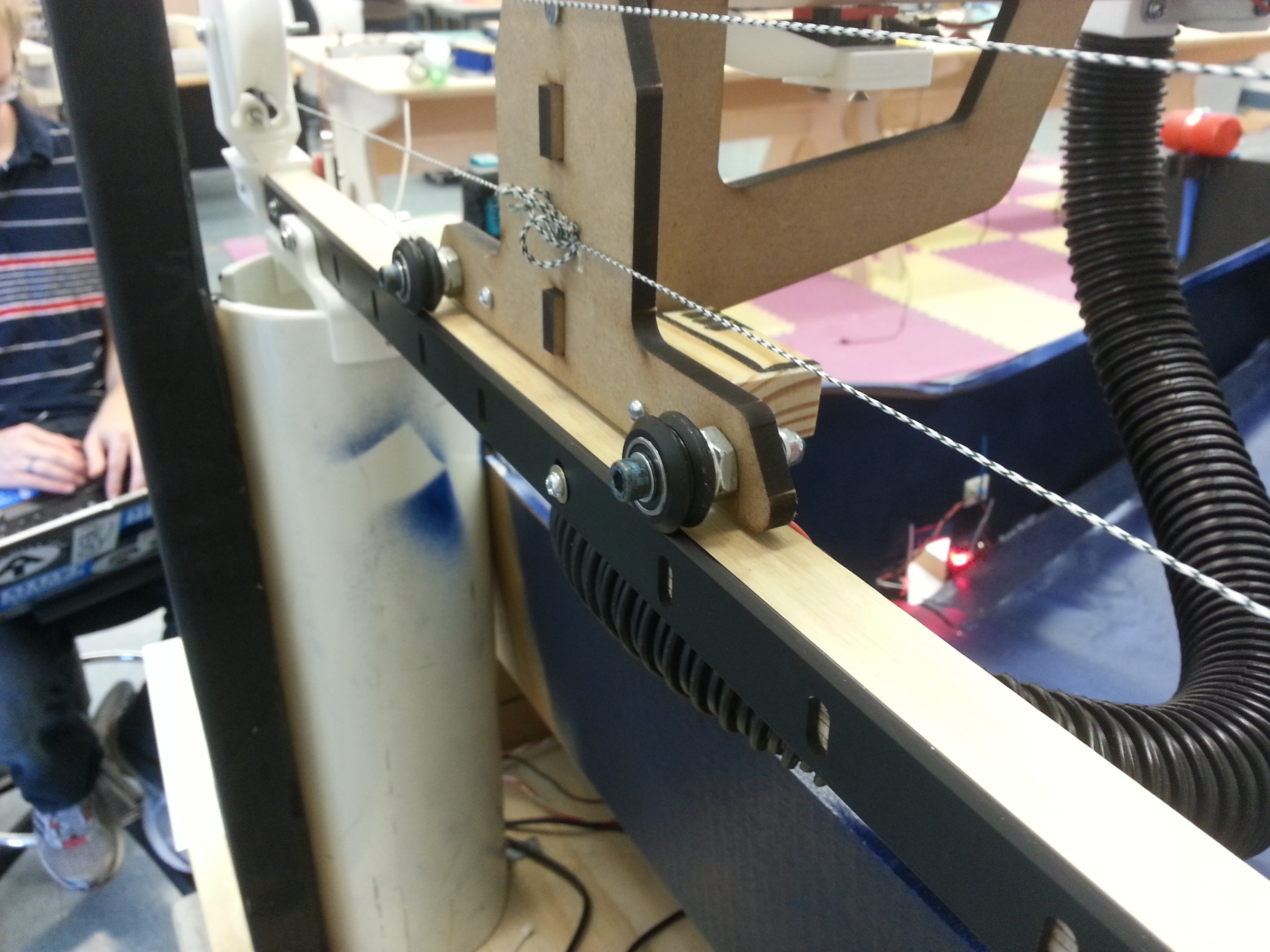
Delrin wheels roll on V rails on both sides of the game to cause a smooth sliding Y axis motion.
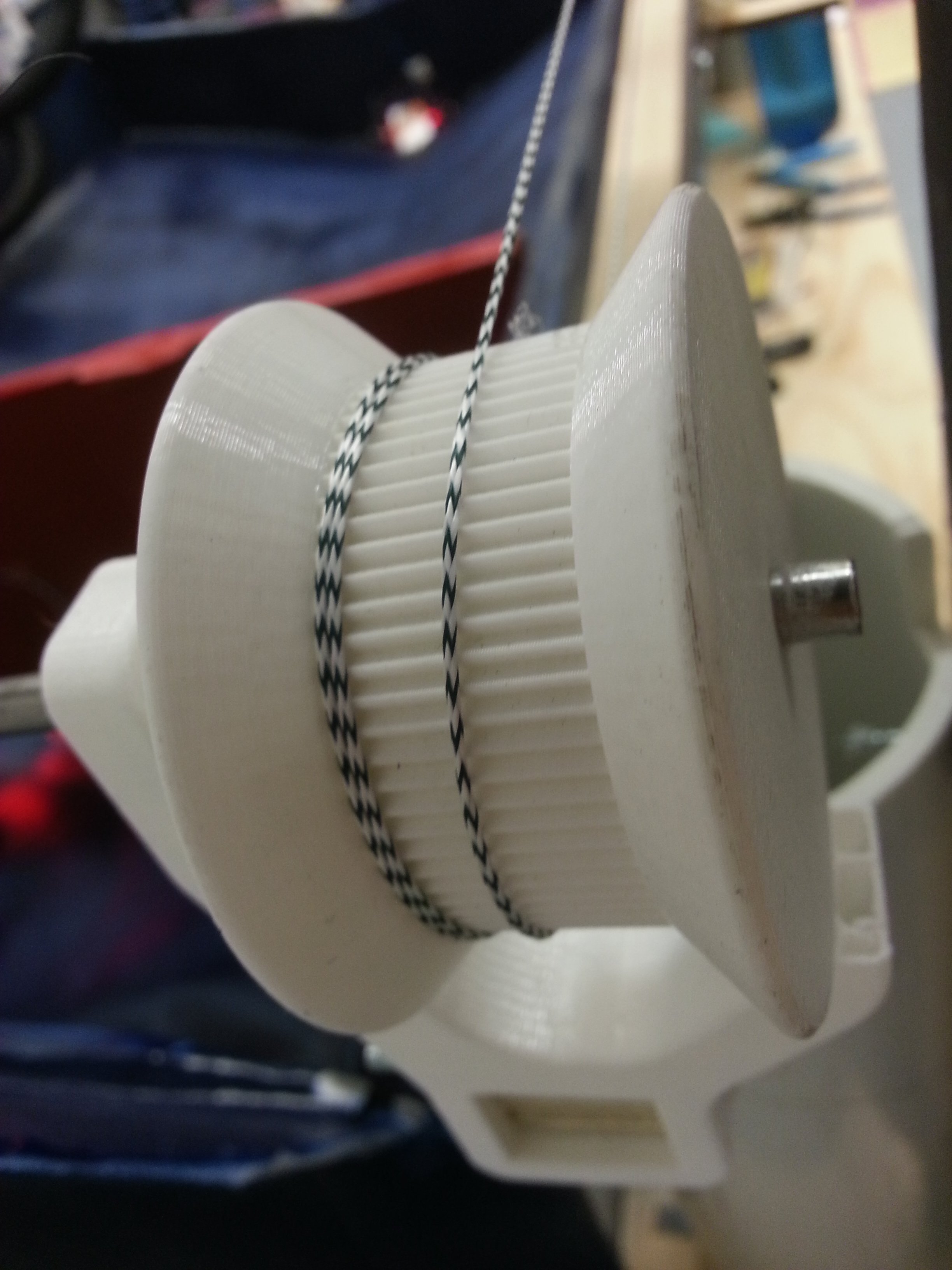
The Y axis was driven with a capstan drive - string is wound several times around a drive pulley and the tension keeps the string from slipping.

Like the X axis, double limit switches provide both software and hardware limits.
The Y axis travels along extruded aluminum V rails, purchased from OpenBuilds, an open source provider of CNC hardware. The X axis (discussed above) was pulled along the parallel V rails using a double capstan drive. In order to prevent torquing forces on the X axis, which was fairly wide, the drive torque from the motor was transferred equally from one side to the other using a long drive shaft. It was very difficult to get the V rails to line up exactly parallel along the entire length, so a system redesign should definitely include a way to adjust the relative position of the V rails to prevent the X axis from driving off the rails.
The Z axis height of the ball was controlled by adjusting the airflow through our nozzle. This was done by placing a redirection gate just downstream of our air source, a Bucket Head Wet/Dry vacuum. A servo controlled how much the airflow was redirected, which adjusted the height of the ball.
The levitating ping pong ball is suspended on a column of air shot out of this funnel. Multiple iterations went into the funnel to get a design with a long range and stable airstream.
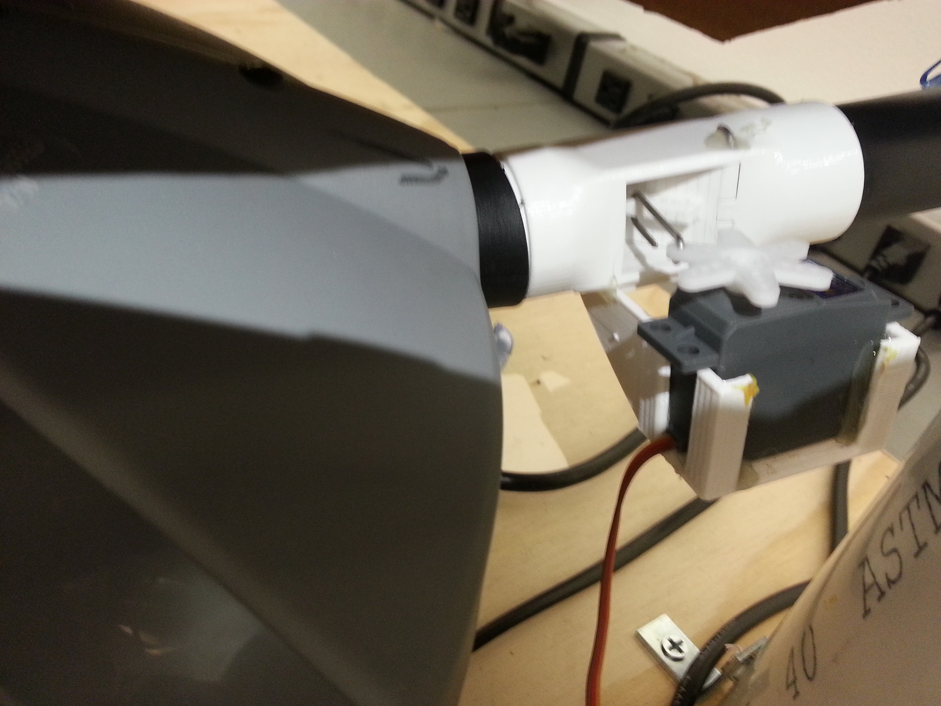
The column of air is driven with a vacuum pushing air out. A servo-driven gate blocks a portion of the airstream, allowing the user to reliably asjust the height of the floating ping pong ball.
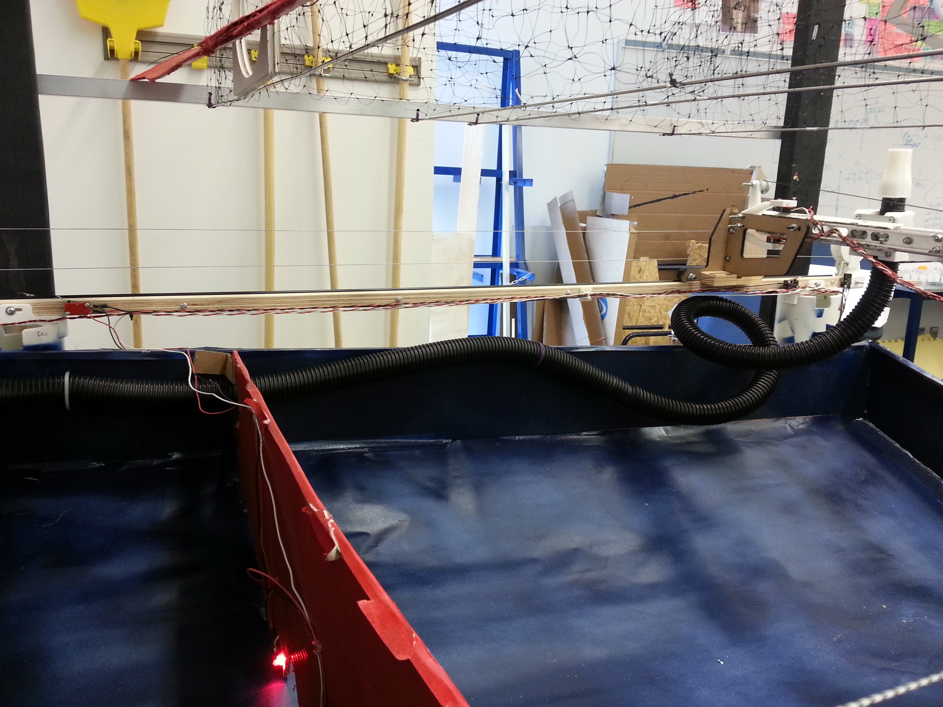
The flexible vacuum tube allows the funnel to easily move across the large X, Y expanse of the game.
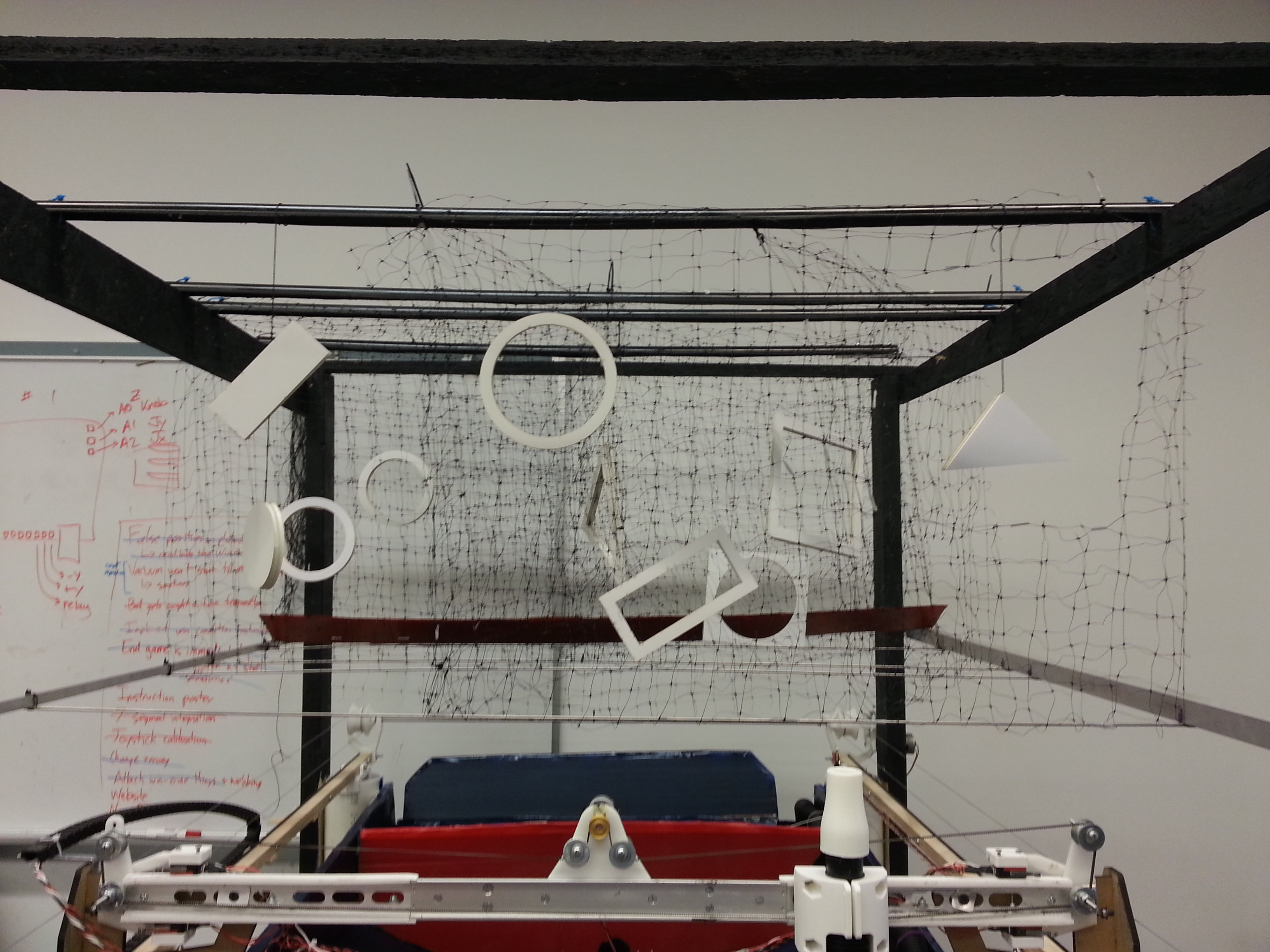
The final obstacle layout for the game.

One way of making obstacles was to hang foam core cutouts in open gaps. These cutouts would flap and gyrate in the air column, which could knock the ping pong ball off.
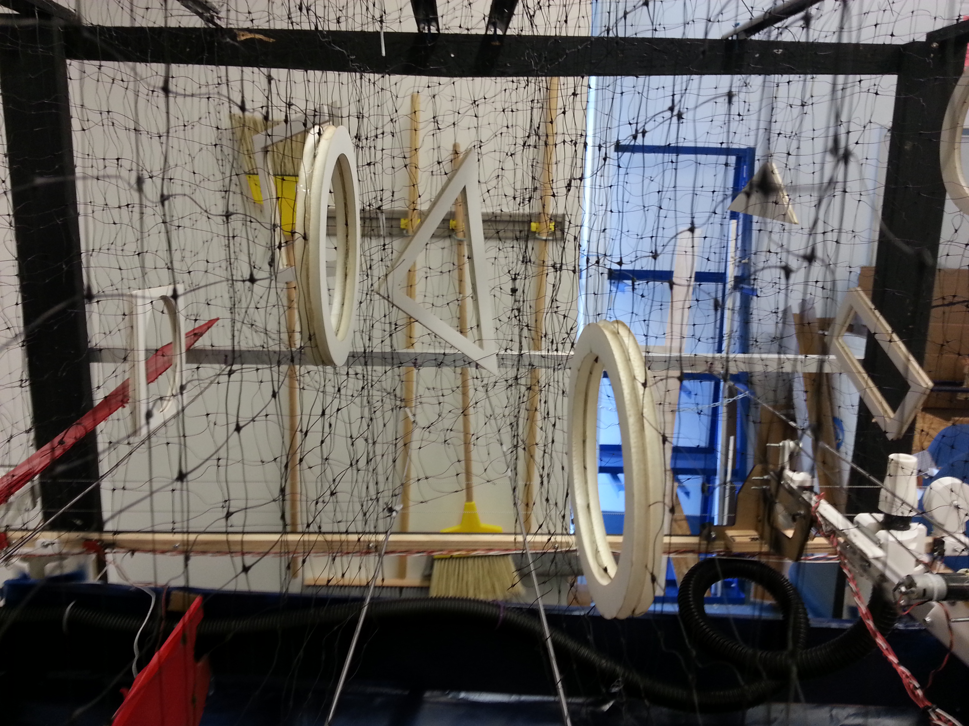
Another way of making obstacles was to glue two sections of foam core together on either side of the net, then cut out the inner net fibers to create a passageway.
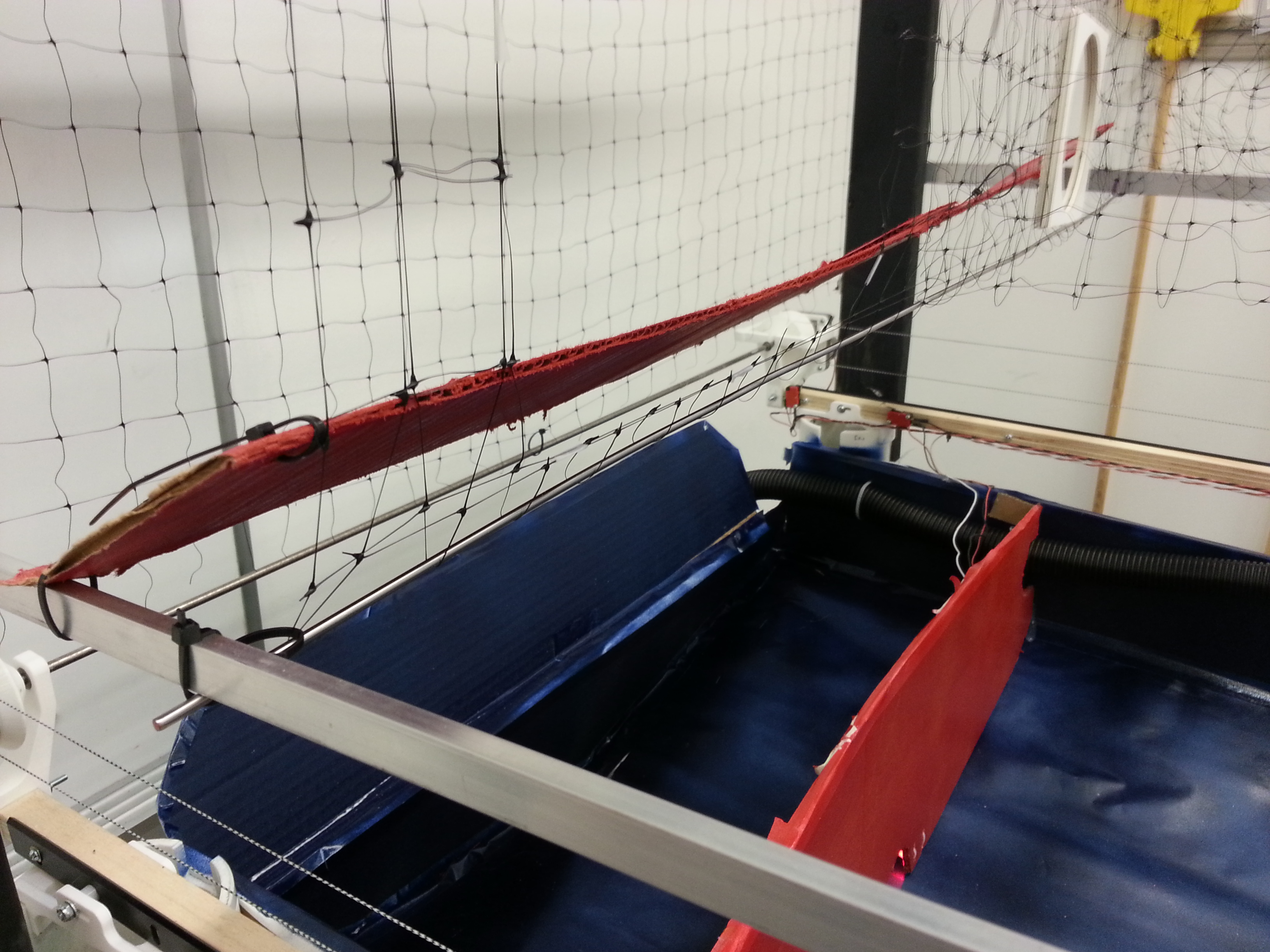
Finally, a cardboard ramp knocks the ping pong ball off of the airstream when the user drives over it, into the waiting goal area. Landing the ball in this back goal area wins the game.
Finally, the obstacles were made from folded string mesh with foam core cutouts for gates. These materials were chosen because they were light, and the mesh was chosen because the user needs to be able to see through the walls so that they can see multiple layers of obstacles. It became clear during gameplay that being able to constantly readjust the maze would make playing more enjoyable, because the course would always be novel, but it is very difficult to physically adjust the obstacles.
Electrical Subsystem
Coin Acceptor
An off the shelf coin acceptor was bought from Sparkfun in order to interface with the main controller to detect certain coins. The acceptor is powered with a 12V source and outputs a small (40mV) pulse whenever a correct coin is inserted. This pulse is amplified through a comparator and then sent to a digital input on the main microcontroller.
Joystick
The x and y axes of the joystick act as variable resistors between 0 and 100k. These resistors are hooked up in a resistor divider configuration with a 3.3V upper rail in order to get a linear* representation of the joystick’s movement. These values are then sent to analog pins on the main microcontroller and used to control the X and Y axis motors. (*we found that the response from the joystick was anything but linear, and it had to be carefully calibrated in order to get an acceptable range of readings from it.
Air Flow Knob
The air flow knob is a potentiometer with a 3.3V rail. The voltage from the wiper of the potentiometer is hooked up directly an analog pin. This creates a linear relationship between the wiper voltage and the rotational angle of the potentiometer. This value is used to control the PWM to a servo which controls the airflow.
Ball Sensors
Photodiode and red LEDs were used to detect when the ball pasted certain sections of the maze. The photodiodes were connected up to transistors in order amplify the signal and then passed into digital pins of the microcontroller.
Limit Controls
There are a number of limit switches that detect when the system reaches the maximum points on the x and y axes. These switches prevent the system from traversing too far and also help zero the system. At each of the 4 maximum points, there are two limit switches - one software and one hardware. The software motor runs back to the main microcontroller, so that the system can intelligently allow the user to drive backwards but no farther forwards. The hardware limit switch is wired directly into the appropriate motor, such that the system cannot move once it has reached that point (and must be manually reset).
System Wiring
We designed and fabricated a PCB in order to make the wiring process cleaner. The PCB contains 2 motor controller drivers, 2 op-amp buffers for the joystick, 1 comparator for the coin acceptor, and a spare op-amp buffer. The rest of the wiring is soldered onto protoboards. Wires that need to be routed to the X axis (which itself is moving over the Y axis) run through a cable chain carrier so that they don't become tangled.
Firmware Subsystem
For this project, we used a custom Arduino-compatible PIC board as our main firmware components. We used two of these boards - one was for user input and game actuation, and the other was for score detection and user display.Main PIC
The main PIC is primarily responsable for actuation. It gets the user's input from the X and Y axes of the joystick and the Z knob, and adjusts the corresponding axes appropriately. The software limit switches are connected to the main PIC as well so that it can disable motion when a limit switch is triggered. When the game starts, the main PIC must zero the axes so that the user can put a ball on the nozzle.
Score PIC
As its name suggests, the score PIC deals with the user's score. It displays the high score and the user's current score (as well as various other snarky ph) on two 7-segment displays. The photodiodes connect to the score PIC in order to detect when the game has ended, and the coin acceptor connects as well to detect when the game should start. Additionally, there is feedback between the two PICs: the score PIC knows when the vacuum turns on via the relay, and the score PIC pulls a dedicated line high / low to indicate that the game is starting / has ended.
Control Tools
We recognized that with a project this large, it would be easy to start creating non-DRY code - or worse, spaghetti code. As a result, we encapsulated all of the functions that took input or sent output into a series of reusable libraries that we called Control Tools. This library is included in the codebase of both our main and our score PICs.