SO:X
Electrical System
Where do all the electrons go?.
Block Diagram
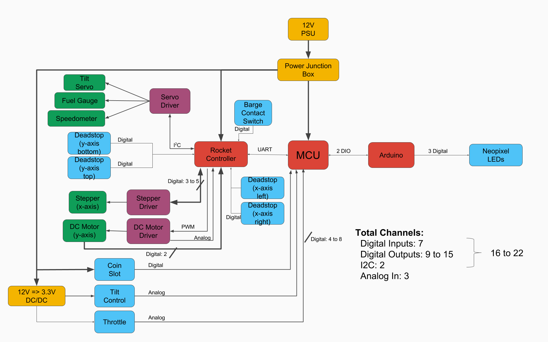
System Overview
Our electrical system is composed of two PICs and an Arduino Uno. The ‘master’ PIC (MCU in the above block diagram) is primarily responsible for UI inputs. It is connected to the throttle button, the tilt joystick, and the coin acceptor. It relays these signals to the rocket controller PIC via UART. The ‘rocket’ PIC is responsible for motor control.
The rocket PIC contains the kinematic rocket model and is connected to the DC motor, stepper motor, servo driver, and endstops. Based on the user inputs received from the master, the rocket PIC controls the speed and orientation of the rocket. The stepper motor controls the x-axis motion of the rocket, while the DC motor controls the y-axis motion of the rocket. The servo controls the tilt and orientation of the rocket based off of the commands from the tilt joystick. There are four total endstops in place that will prevent the motor from driving past the limits of the physical gantry and causing damage to the system. The fifth and final endstop is mounted on the barge, and detects whether or not the rocket has landed on the platform. When the barge switch has been pressed, the system then determines a win or lose condition based off of the speed and tilt variables contained within the kinematic model. In addition, the rocket PIC keeps track of rocket fuel and speed, and displays these values to the user via two dials controlled by servos.
During a win or lose event, the rocket PIC relays its state the master, which then sets the appropriate digital I/O pins high or low to communicate the state to the arduino. The Arduino then drives the Neopixel LEDs appropriately with three digital output pins. There are three strips of LEDs, one on the barge to indicate a win or a loss to the user, one on the UI panel to indicate number of lives, and one on the rocket. The LEDs on the barge glow green during a win state, and red during a lose state. During the flying state, the barge LEDs are white, and blue during the reset state. The lives light up green based off of the number of attempts the user has remaining. Finally, the rocket LED is a single LED which, during the flying state, glows orange when the throttle button has been pushed.