

The goal of this project was to build a mechanical penny arcade game with a well designed, compelling gameplay experience. The game we designed and built was a game where you attempt to jump over a rope as many times as possible. This website documents the work our team did to create this system.
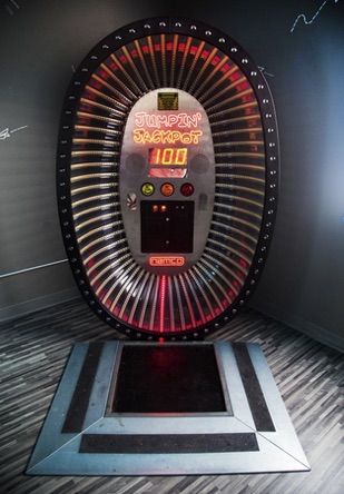
The game we created was based on the Jumpin' Jackpot arcade game. In Jumpin' Jackpot, a series of LEDs turn on in a circle to simulate a jump rope. The player jumps over the moving lights, similar to how you would jump rope. The goal of the game is to jump as many times as possible, with the lights moving faster and faster. Jumpin' Jackpot takes the analog activity of jump rope, and makes it digital for the purposes of an arcade game. We were interested in recreating the game, but incorporating an actual jump rope. Another aspect of this game we found compelling was the fact that the player is actually a part of the game. There are no controls that the player is engaging with, and all you have to do to play is jump!
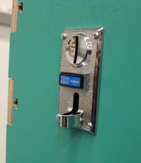
The goal of this game is to jump over the rope as many times as possible as it swings back and forth. The game is composed of a platform the user jumps on, two simultaneously swinging pendulum arms, a control panel, and a rope with a break point. The user begins by inserting a coin. The two swing arms move 30 degrees towards the user, and wait for the rope to be reconnected. Once the rope is reconnected, the rope moves 90 degrees in the other direction. The user then enters the platform and presses the start button to begin. Between each swing, the arms pauses. As the user gets further along in the game, these pause amounts get shorter and shorter. The scoreboard keeps track of the number of sucessful jumps, until the rope is broken.
The three major components of this project can be broken up into mechanical, electrical and software groups and all work together to make the game work.
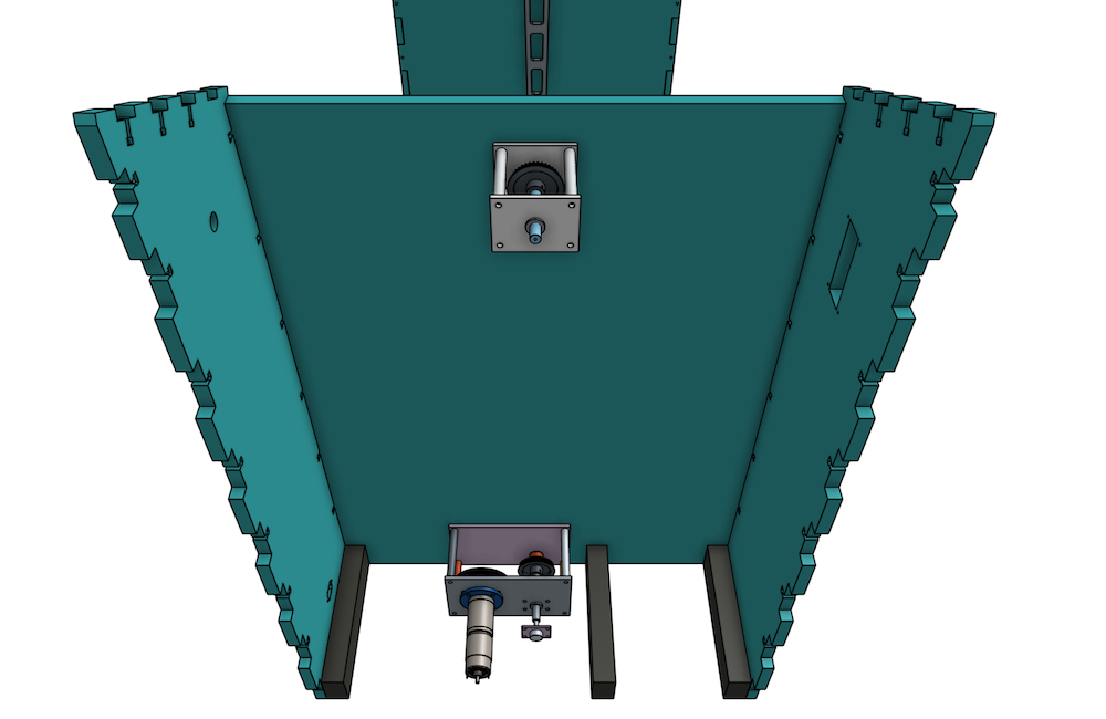
The mechanical system is composed of a plywood and 2x3 frame with an integrated transmission. The 2x3 frame raises the floor by 2 inches in order for a install a drive shaft. In each of the two consoles on either side are two clockcages to drive the swing arms. The CAD of the system can be found here.
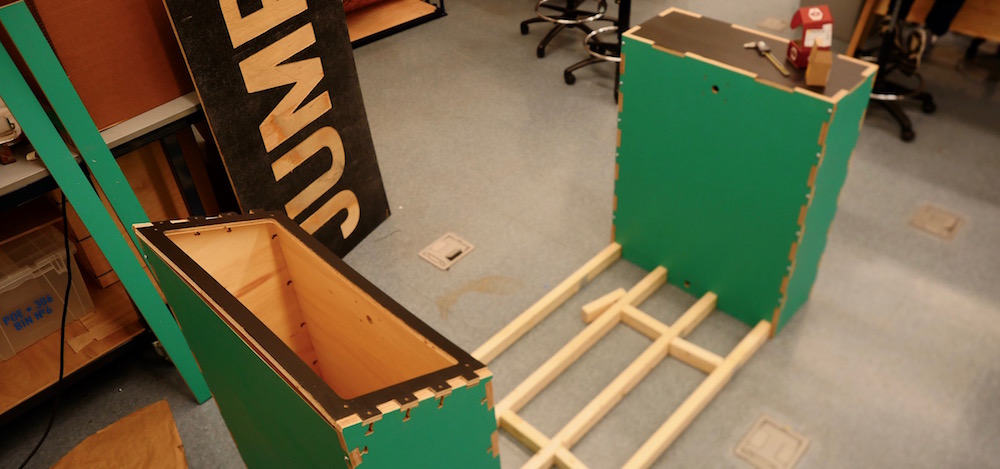
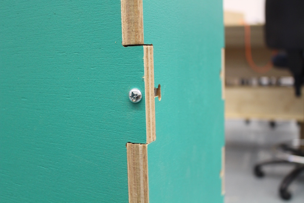
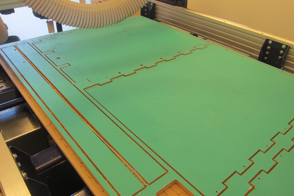
The frame itself is constructed of 3/4'' and 1/2'' hardwood plywood and 2x3 lumber. The lumber provides the support for the raised floor, and the plywood creates the structure of the two consoles on either side of the floor. The plywood is assembled using 1/4''x20s and square nuts holding together the finger joint at each edge. The floor frame is wood screwed to the consoles, and the floor is screwed to the floor. The plywood frame pieces were built using a CNC router, and assembled with a combination of bolts and wood screws.
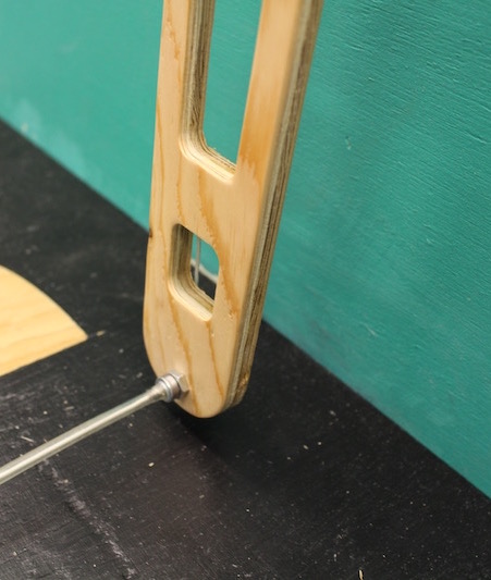
The transmission allows for both swing arms to be driven in unison using only one motor. The motor is connected to the main drive shaft via a 5mm HTD timing belt and pulleys with a 4:1 gear ratio. This gear ratio reduces the torque of the motor and speeds up the system’s swings so that it is comfortable to jump over. To connect the swing arms to the main drive shaft, we used timing belts and pulleys with a 1:1 gear ratio.
The transmission is made up of 4 clockcages that are mounted within the game’s consoles. Three of these are identical, consisting of two laser cut acrylic plates, 4 aluminum standoffs, and two bronze bushings to support the shafts. The last clockcage is made using two milled aluminum plates as it also serves as the motor mounting point and connection to the main drive shaft that runs the length of the machine. The motor and shafts were connected to each other via 5mm HTD timing belts and pulleys, which were selected for cost, availability, and an appropriate load capacity. We purchased the pulleys that connect the main drive shaft to each of the swing arm shafts, which have a 1:1 gear ratio. The pulleys that connect the motor to the main drive shaft were printed on a Markforged Mark One, which allowed us to customize the geometry exactly as we wanted. These two pulleys have a 1:4 gear ratio, meaning the torque of our powerful motor is reduced while speeding up the swings of the system. All of the drive shafts were machined using ½” diameter, polished 12L14 steel rod stock. All of the transmission components are fixed to the shafts using spring pins to ensure accurate alignment and eliminate concerns about slipping.
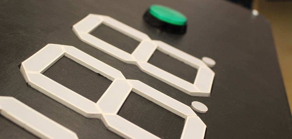
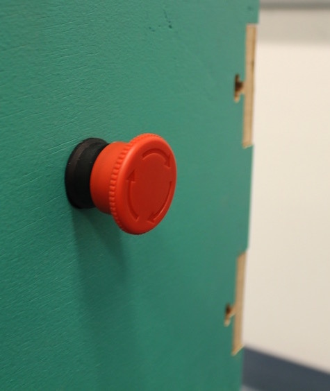
The electrical system consists of our display board, which houses our EXTREMELY large seven segment displays (we are very excited about these), our indicator LEDS, and a button to start game play, as well the coin slot, and our end of play sensor. We chose to utilize the interaction of hitting the rope to indicate when play ended. To accomplish this, we created an electrical connection through the rope itself, with a magnetic break point at one end. When this connection is broken, a trigger is sent to our PIC to indicate that a player has lost.
The circuit diagram for our system is outlined below:

The state diagram for our software system is illustated below. Our code can be found on our github respository here

One of the early decisions we had to make as a team was how to drive the swing arms of the system. Since we were using a rope meant to disconnect when it hits the player, the swinging motion of the two arms needed to be as close to perfect unison as possible. If one arm was swinging faster than the other, the rope would likely be pulled apart before the player could even complete one jump. Initially we intended to drive each swing arm with its own dedicated motors, as this would simplify the mechanical design of the system. However, this implementation had us concerned over our abilities to control the motors perfectly from the PIC. We would need to accurately sense the angular position of each swing arm over time as well create an appropriate control scheme to keep the two arms at the same position at all times. During our very first design review, a fellow student suggested the idea of a single motor with a drive shaft and transmission that moves the two arms. Due to the size and skillset of our time, we decided that this was a much smarter idea. Our mechanical engineers were confident that they could build a robust system that would keep the two swing arms moving in unison using a long drive shaft that runs through the entire system, and timing belts to transmit the motion to the arms. Ultimately, this system was what we chose to implement (more details above) and we were successful in achieving our project goals.
Because of the physical nature of our game, the addition of safety precautions was a crucial consideration during design. The rope we use is a big part of that. It needed to be substantial enough to not get damaged with the wear of being caught under people’s feet, but we also needed to make a system that would prevent tripping. Our solution was to design a rope that had an intentional break point which would trigger the end of the game and the shutdown of our motors. When designing this break point, we had to choose between the use of magnets and metal snaps, taking into consideration what would provide the proper force to break when necessary without breaking during the swinging motion. We chose magnets because we decided that snaps would not necessarily respond to force from the side as well as magnets would. We believed that magnets would be guaranteed to break with the force of hitting a leg, while snaps might not.
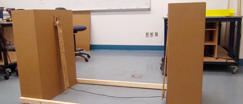
Once we had a concept in mind, we had to decide how big the entire system needed to be in order for a person to comfortably play our game. Because the user is the controller in this game, it was really important that we didn't overlook any major aspects of the size of the game. In order to do that, we prototyped the entire frame out of cardboard in order to test out how big the consoles needed to be, how wide the jump space needed to be, and approximately how long the swing arms needed to be. Without this initial testing, we would have had no idea how big of a system to create, and could have created a final system that people were physically unable or uncomfortable to jump in. The system ended up being approximately 6.5 ft. long, 2 ft. wide and 3.5 ft. tall.
This project was done for the Elecanisms class at Olin College of Engineering. Over the course of about 8 weeks, we designed and built this game. The team was composed of two mechanical engineers: Sean Karagianes and Adit Dhanushkodi, and two electrical and computer engineers: Saarth Mehrotra and Cameron Anderson. Thanks to Aaron Hoover, Brad Minch, Forrest Bourke, Doyung Lee, and the Stockrooms at Olin for all your help with this project.